Toyota Venza: Back Door Support
Components
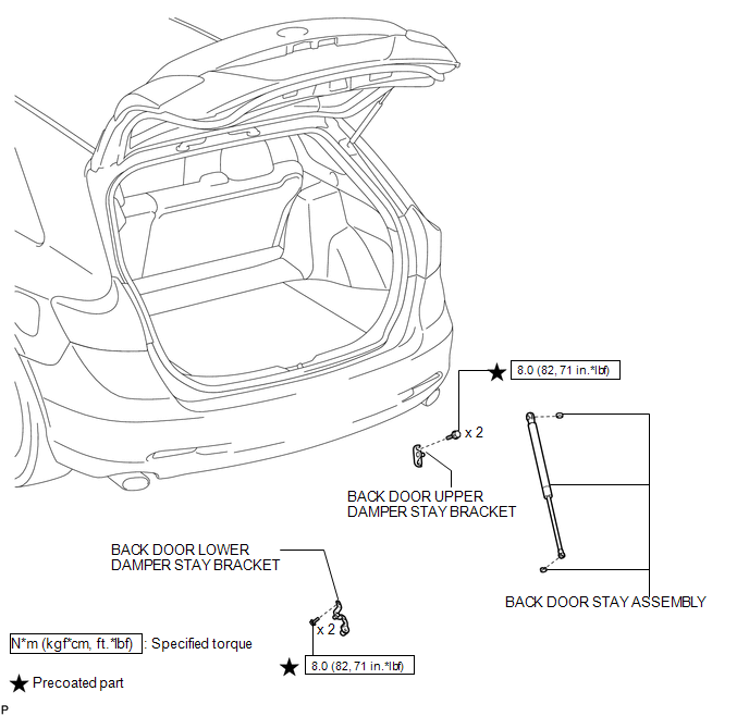
COMPONENTS
ILLUSTRATION
Removal
REMOVAL
PROCEDURE
1. REMOVE BACK DOOR STAY ASSEMBLY
NOTICE:
- Avoid touching the piston rod as much as possible to prevent foreign matter from attaching to it. Be sure to hold the cylinder while servicing.
- Do not wear cotton gloves or other similar materials when handling the piston rod. Fibers may attach to the rod and result in gas leaks.
- Do not apply any horizontal load to the door stay in order to prevent the piston rod from deforming.
|
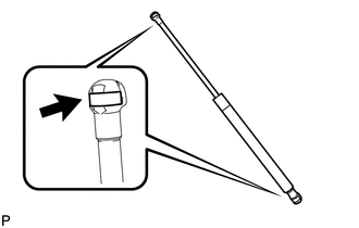
(a) Using a screwdriver, remove the stop ring along the groove. HINT: Tape the screwdriver tip before use. Text in Illustration
|
|
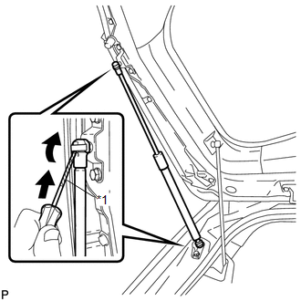
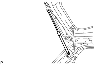
(b) Release the ball joint and remove the back door stay assembly.
NOTICE:
Remove the back door stay assembly while supporting the back door by hand.
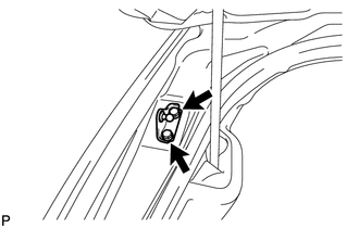
2. REMOVE BACK DOOR LOWER DAMPER STAY BRACKET
|
(a) Remove the 2 bolts and back door lower damper stay bracket. |
|
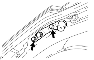
3. REMOVE BACK DOOR UPPER DAMPER STAY BRACKET
|
(a) Remove the 2 bolts and back door upper damper stay bracket. |
|
Disposal
DISPOSAL
PROCEDURE
1. DISPOSE OF BACK DOOR STAY ASSEMBLY
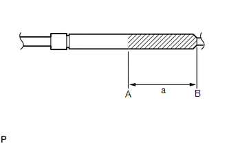
(a) Secure the back door stay assembly horizontally in a vise with the piston rod pulled out.
|
(b) Wear safety glasses. Use a metal saw to slowly cut a groove between A and B shown in the illustration to release the gas. Standard Dimension: a 80.0 mm (3.150 in.) NOTICE: Although the gas inside the back door stay assembly is colorless, odorless and harmless, metal debris may scatter. Therefore, cover the back door stay assembly with a piece of cloth or other material. |
|
Installation
INSTALLATION
PROCEDURE
1. INSTALL BACK DOOR UPPER DAMPER STAY BRACKET
(a) Clean the threaded portion on the vehicle body with a non-residue solvent.
(b) Apply adhesive to the threads of the 2 bolts.
Adhesive:
Toyota Genuine Adhesive 1324, Three Bond 1324 or equivalent
|
(c) Install the back door upper damper stay bracket with the 2 bolts. Torque: 8.0 N·m {82 kgf·cm, 71 in·lbf} |
|
.png)
2. INSTALL BACK DOOR LOWER DAMPER STAY BRACKET
(a) Clean the threaded portion on the vehicle body with a non-residue solvent.
(b) Apply adhesive to the threads of the 2 bolts.
Adhesive:
Toyota Genuine Adhesive 1324, Three Bond 1324 or equivalent
|
(c) Install the back door lower damper stay bracket with the 2 bolts. Torque: 8.0 N·m {82 kgf·cm, 71 in·lbf} |
|
.png)
3. INSTALL BACK DOOR STAY ASSEMBLY
NOTICE:
- Avoid touching the piston rod as much as possible to prevent foreign matter from attaching to it. Be sure to hold the cylinder while servicing.
- Do not wear cotton gloves or other similar materials when handling the piston rod. Fibers may attach to the rod and result in gas leaks.
- Do not apply any horizontal load to the door stay in order to prevent the rod from deforming.
(a) When reusing the back door stay assembly:
|
(1) Install the 2 stop rings to the back door stay assembly. |
|
|
(b) Install the back door stay assembly. NOTICE: Install the back door stay assembly while supporting the back door by hand. |
|
(c) Check that the back door stay assembly is engaged in the ball joint and that the back door stay assembly cannot be pulled out.
 Back Door Opener Switch
Components
COMPONENTS
ILLUSTRATION
Removal
REMOVAL
PROCEDURE
1. REMOVE BACK DOOR PANEL TRIM ASSEMBLY
2. REMOVE REAR LIGHT ASSEMBLY LH
3. REMOVE REAR LIGHT ASSEMBLY RH
HINT:
Use t ...
 Front Door
...
Other materials about Toyota Venza:
Removal
REMOVAL
CAUTION / NOTICE / HINT
NOTICE:
Do not replace the spiral cable with the battery connected and the ignition
switch ON.
Do not rotate the spiral cable without the steering wheel with the battery
connected and the ignition switch O ...
Replacement
REPLACEMENT
PROCEDURE
1. REPLACE INTAKE VALVE GUIDE BUSH
(a) Heat the cylinder head to approximately 80 to 100°C (176 to 212°F).
(b) Place the cylinder head on wooden blocks.
(c) Using SST and a hammer, tap out the valve guide bush.
SST: 0 ...
Types of child restraints
Child restraint systems are classified into the following 3 types according to
the age and size of the child.
► Rear facing -- Infant seat/convertible
seat
► Forward facing -- Convertible seat
► Booster seat
- When install ...

0.1662