Toyota Venza: Precaution
PRECAUTION
1. PRECAUTION FOR VEHICLE WITH SRS AIRBAG AND SEAT BELT PRETENSIONER
(a) Some operations in this section may affect the SRS airbags. Prior to performing
the corresponding operations, read the precautions regarding the SRS airbags (See
page .gif) ).
).
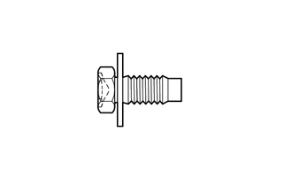
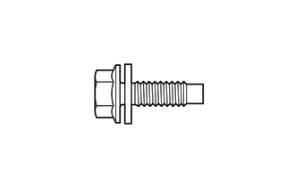
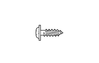
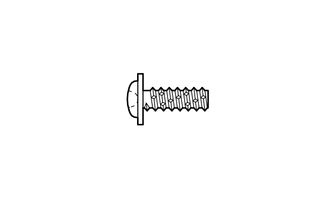
2. TABLE OF BOLT, SCREW AND NUT
HINT:
All bolts, screws and nuts relevant to installing and removing the instrument panel are shown along with their alphabet code in the table below.
|
Code |
Shape |
Size |
Code |
Shape |
Size |
|---|---|---|---|---|---|
|
<A> |
 |
φ = 8 mm (0.315 in.) Length = 20 mm (0.787 in.) |
<B> |
 |
φ = 8 mm (0.315 in.) Length = 25 mm (0.984 in.) |
|
<C> |
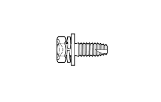 |
φ = 6 mm (0.236 in.) Length = 18 mm (0.709 in.) |
<D> |
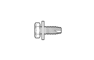 |
φ = 6 mm (0.236 in.) Length = 15 mm (0.591 in.) |
|
<E> |
 |
φ = 5 mm (0.197 in.) Length = 16 mm (0.630 in.) |
<F> |
 |
φ = 5 mm (0.197 in.) Length = 14 mm (0.551 in.) |
|
<G> |
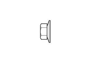 |
φ = 6 mm (0.236 in.) |
<H> |
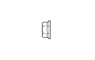 |
φ = 6 mm (0.236 in.) |

 Components
COMPONENTS
ILLUSTRATION
ILLUSTRATION
ILLUSTRATION
ILLUSTRATION
ILLUSTRATION
ILLUSTRATION
ILLUSTRATION
ILLUSTRATION
ILLUSTRATION
ILLUSTRATION
...
Other materials about Toyota Venza:
Air Fuel Ratio Sensor
Components
COMPONENTS
ILLUSTRATION
Removal
REMOVAL
PROCEDURE
1. REMOVE NO. 1 ENGINE COVER SUB-ASSEMBLY
2. REMOVE COOL AIR INTAKE DUCT SEAL
3. REMOVE INLET AIR CLEANER ASSEMBLY
4. REMOVE NO. 1 EXHAUST MANIFOLD HEAT INSULATOR
5. REMOV ...
Tongue Plate Stopper
Components
COMPONENTS
ILLUSTRATION
Replacement
REPLACEMENT
PROCEDURE
1. REMOVE TONGUE PLATE STOPPER
(a) Slide the tongue plate above the installation position of the tongue
plate stopper, and temporarily hold it with adhesive tape.
...
Removal
REMOVAL
PROCEDURE
1. REMOVE FRONT SEAT HEADREST ASSEMBLY
2. REMOVE FRONT SEAT REAR OUTER TRACK COVER
3. REMOVE FRONT SEAT REAR INNER TRACK COVER
4. REMOVE FRONT SEAT ASSEMBLY
5. REMOVE RECLINING POWER SEAT SWITCH KNOB
6. REMOVE SLIDE AND VER ...

0.1512