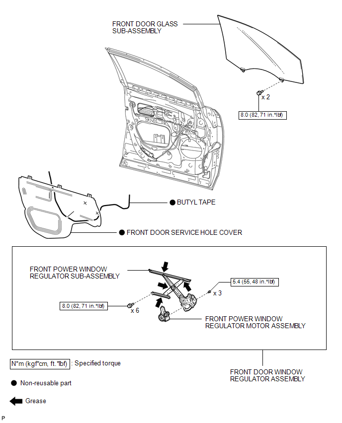
Toyota Venza: Components
COMPONENTS
ILLUSTRATION
.png)
ILLUSTRATION

 Removal
REMOVAL
CAUTION / NOTICE / HINT
HINT:
Use the same procedure for the RH side and LH side.
The procedure listed below is for the LH side.
PROCEDURE
1. DISCONNECT CABLE FROM NEGAT ...
Other materials about Toyota Venza:
Disassembly
DISASSEMBLY
PROCEDURE
1. REMOVE SEAT ADJUSTER COVER CAP LH
(a) Using a screwdriver wrapped with protective tape, disengage the 3
claws and remove the seat adjuster cover cap LH.
Text in Illustration
*1
...
Certification ECU Vehicle Information Reading/Writing Process Malfunction (B15F7)
DESCRIPTION
This DTC is stored when items controlled by the certification ECU (smart key
ECU assembly) cannot be customized via the audio and visual system vehicle customization
screen.
HINT:
The certification ECU (smart key ECU assembly) controls the s ...
Installation
INSTALLATION
PROCEDURE
1. INSTALL OUTER REAR VIEW MIRROR ASSEMBLY
(a) Engage the 3 claws to install the outer rear view mirror assembly
as shown in the illustration.
(b) Install the 3 nuts.
Tor ...

0.1288