Toyota Venza: Components
COMPONENTS
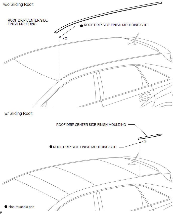
ILLUSTRATION

 Removal
REMOVAL
PROCEDURE
1. REMOVE ROOF DRIP CENTER SIDE FINISH MOULDING (w/o Sliding Roof)
(a) Put protective tape around the roof drip center side finish moulding.
Text in Illustration
...
Other materials about Toyota Venza:
Dtc Check / Clear
DTC CHECK / CLEAR
1. CHECK DTC
(a) Connect the Techstream to the DLC3.
(b) Turn the ignition switch to ON.
(c) Turn the Techstream on.
(d) Enter the following menus: Body Electrical / Back Door / DTC.
HINT:
Refer to the Techstream operator's manual ...
Solar Sensor
Components
COMPONENTS
ILLUSTRATION
On-vehicle Inspection
ON-VEHICLE INSPECTION
PROCEDURE
1. INSPECT SOLAR SENSOR
(a) Disconnect the solar sensor connector.
(b) Measure the voltage accordin ...
How To Proceed With Troubleshooting
CAUTION / NOTICE / HINT
HINT:
*: Use the Techstream.
PROCEDURE
1.
VEHICLE BROUGHT TO WORKSHOP
NEXT
2.
CUSTOMER PROBLEM ANALYSIS
...

0.1145