Toyota Venza: Components
COMPONENTS
ILLUSTRATION
ILLUSTRATION
ILLUSTRATION
ILLUSTRATION
.png)
ILLUSTRATION
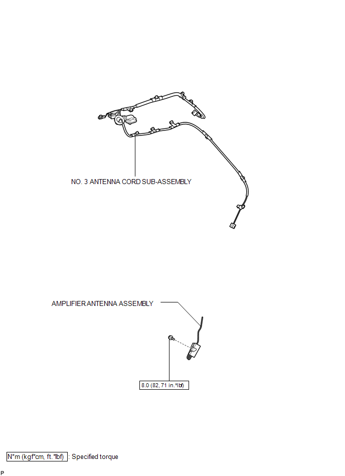
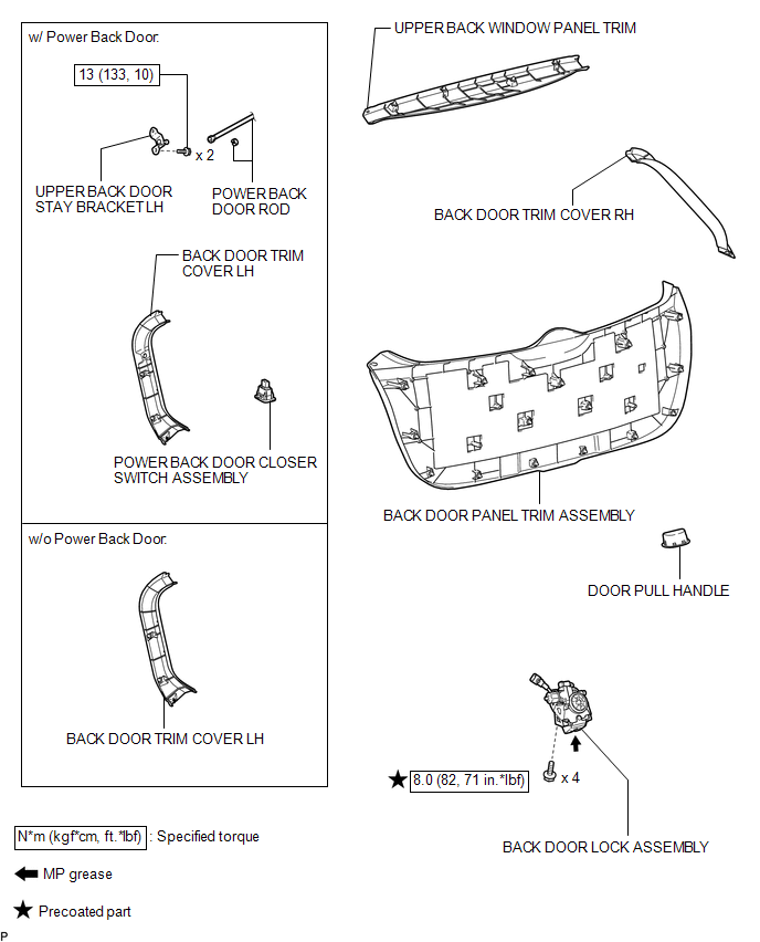
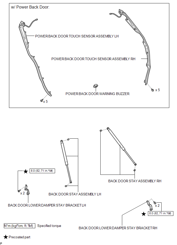
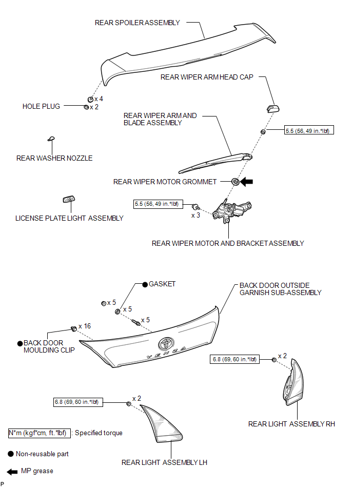
 Back Door
...
 Adjustment
ADJUSTMENT
CAUTION / NOTICE / HINT
HINT:
Use the same procedure for the RH side and LH side.
The following procedure is for the LH side.
Centering bolts are used to mount the do ...
Other materials about Toyota Venza:
Touch Panel Switch does not Function
PROCEDURE
1.
CHECK MULTI-DISPLAY
(a) Check if there is any foreign matter caught between the display and exterior
frame of the multi-display.
OK:
No foreign matter is caught between the display and exterior frame of the m ...
A/C ECU Vehicle Information Reading/Writing Processor Malfunction (B15F5)
DESCRIPTION
This DTC is stored when items controlled by the air conditioning amplifier assembly
cannot be customized via the navigation system vehicle customization screen.
HINT:
The air conditioning amplifier assembly controls the air conditioning system ...
Abbreviations Used In Manual
ABBREVIATIONS USED IN MANUAL
Abbreviation
Meaning
ABS
Anti-Lock Brake System
A/C
Air Conditioner
AC
Alternating Current
ACC
A ...

0.1592