Toyota Venza: Engine Coolant Temperature / Intake Air Temperature Correlation (P011B)
DESCRIPTION
The engine has two temperature sensors, an engine coolant temperature sensor and an intake air temperature sensor, to detect the temperature while the engine is in operation. A thermistor, whose resistance value varies according to the temperature, is built into each sensor. When the temperature is low, the resistance of the thermistor increases. When the temperature is high, the resistance drops. These variations in resistance are transmitted to the ECM as voltage changes. Based on these temperature signals output from the sensors, the ECM determines the fuel injection time and the ignition timing to control the engine.
|
DTC No. |
DTC Detection Condition |
Trouble Area |
|---|---|---|
|
P011B |
|
|
HINT:
- Waiting is required to prevent the temperature of the engine from affecting the readings. If the engine has been operated recently, it is not possible to accurately compare the readings.
- For diagnosis, in order to duplicate the detection conditions of the DTC, it is necessary to park the vehicle for 7 hours. Parking the vehicle for 7 hours ensures that the actual temperature of the engine coolant temperature and intake air temperature are very similar. When the vehicle has been parked for less than 7 hours, differences in the readings may exist, but this does not necessarily indicate a fault.
MONITOR DESCRIPTION
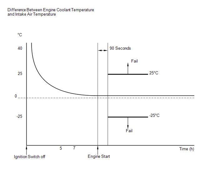
The ECM monitors the difference between the engine coolant temperature and the intake air temperature when the engine is started cold to accurately detect the engine temperature conditions. The monitor runs when the engine started cold after 7 hours or more have elapsed since the engine was stopped (ignition switch turned off) on the previous trip. If the difference between the engine coolant temperature and the intake air temperature on a cold start exceeds 25°C (45°F), the ECM interprets this as a malfunction in the engine coolant temperature sensor circuit and intake air temperature sensor circuit, and stores the DTC.
MONITOR STRATEGY
|
Related DTCs |
P011B: Engine Coolant Temperature/Intake Air Temperature Sensor Correlation |
|
Required Sensors/Components (Main) |
Engine coolant temperature sensor Intake air temperature sensor |
|
Required Sensors/Components (Related) |
- |
|
Frequency of Operation |
Once per driving cycle |
|
Duration |
- |
|
MIL Operation |
2 driving cycles |
|
Sequence of Operation |
None |
TYPICAL ENABLING CONDITIONS
|
Monitor runs whenever the following DTCs are not stored |
None |
|
Both of the following conditions are met |
1 and 2 |
|
1. All of the following conditions are met |
(a), (b), (c) and (d) |
|
(a) After ignition switch ON and engine not running time |
Less than 20 seconds |
|
(b) Soak Time |
7 hours or more |
|
(c) Battery voltage |
10.5 V or higher |
|
(d) Time after engine start |
90 seconds or more |
|
2. Either of the following conditions is met |
(a) or (b) |
|
(a) Minimum intake air temperature after engine start |
-10°C (14°F) or higher |
|
(b) Engine coolant temperature before engine start |
-10°C (14°F) or higher |
|
Engine coolant temperature sensor circuit fail (P0115, P0117, P0118, P0125) |
Not detected |
|
Intake air temperature sensor circuit fail (P0112, P0113) |
Not detected |
|
Mass air flow meter circuit fail (P0102, P0103) |
Not detected |
|
Soak timer fail (P2610) |
Not detected |
TYPICAL MALFUNCTION THRESHOLDS
|
Deviated engine coolant temperature and intake air temperature |
Below -25°C (-45°F), or higher than 25°C (45°F) |
CONFIRMATION DRIVING PATTERN
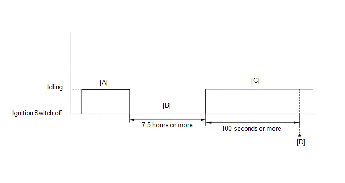
- Connect the Techstream to the DLC3.
- Turn the ignition switch to ON and turn the Techstream on.
- Clear the DTCs (even if no DTCs are stored, perform the clear DTC procedure)
(See page
.gif) ).
). - Turn the ignition switch off.
- With the engine stopped, leave the vehicle as is for 7.5 hours or more [B].
- Turn the ignition switch to ON and turn the Techstream on.
- Start the engine and wait 100 seconds or more [C].
- Enter the following menus: Powertrain / Engine / Trouble Codes [D].
- Read the Pending DTCs.
HINT:
- If a pending DTC is output, the system is malfunctioning.
- If a pending DTC is not output, perform the following procedure.
- Enter the following menus: Powertrain / Engine / Utility / All Readiness.
- Input the DTC: P011B.
- Check the DTC judgment result.
Techstream Display
Description
NORMAL
- DTC judgment completed
- System normal
ABNORMAL
- DTC judgment completed
- System abnormal
INCOMPLETE
- DTC judgment not completed
- Perform driving pattern after confirming DTC enabling conditions
N/A
- Unable to perform DTC judgment
- Number of DTCs which do not fulfill DTC preconditions has reached ECU memory limit
HINT:
- If the judgment result shows NORMAL, the system is normal.
- If the judgment result shows ABNORMAL, the system has a malfunction.
- If the judgment result shows INCOMPLETE or N/A, perform steps [B] through [D] again.
- If no pending DTC is output, perform a universal trip and check for
permanent DTCs (See page ).
HINT:
- If a permanent DTC is output, the system is malfunctioning.
- If no permanent DTC is output, the system is normal.
CAUTION / NOTICE / HINT
HINT:
Read freeze frame data using the Techstream. The ECM records vehicle and driving condition information as freeze frame data the moment a DTC is stored. When troubleshooting, freeze frame data can help determine if the vehicle was moving or stationary, if the engine was warmed up or not, if the air fuel ratio was lean or rich, and other data from the time the malfunction occurred.
PROCEDURE
|
1. |
CHECK ANY OTHER DTCS OUTPUT (IN ADDITION TO P011B) |
(a) Connect the Techstream to the DLC3.
(b) Turn the ignition switch to ON.
(c) Turn the Techstream on.
(d) Enter the following menus: Powertrain / Engine / Trouble Codes.
(e) Read the DTCs.
|
Result |
Proceed to |
|---|---|
|
DTC P011B is output |
A |
|
DTC P011B and other DTCs are output |
B |
HINT:
If any DTCs other than P011B are output, troubleshoot those DTCs first.
| B | .gif) |
GO TO DTC CHART |
|
.gif)
|
2. |
READ VALUE USING TECHSTREAM (INTAKE AIR) |
(a) Leave the vehicle for 7 hours or more.
HINT:
It is necessary to leave the vehicle for 7 hours or more to create conditions similar to the DTC detection conditions.
(b) Connect the Techstream to the DLC3.
(c) Turn the ignition switch to ON.
(d) Turn the Techstream on.
(e) Enter the following menus: Powertrain / Engine / Data List / Intake Air.
(f) Read the value displayed on the Techstream.
OK:
Difference between the intake air temperature and the actual outside air temperature is within 10°C (18°F).
HINT:
- Temperature readings on the outside temperature gauge of the vehicle (if equipped) are not suitable for comparing to the intake air temperature reading. The outside temperature gauge has a significant delay built in to prevent swings in the temperature display. Use an accurate thermometer to determine the outside air temperature.
- Perform "Inspection After Repair" after replacing the mass air flow
meter (See page ).
| NG | |
REPLACE MASS AIR FLOW METER |
|
|
3. |
READ VALUE USING TECHSTREAM (COOLANT TEMPERATURE) |
(a) Connect the Techstream to the DLC3.
(b) Turn the ignition switch to ON.
(c) Turn the Techstream on.
(d) Enter the following menus: Powertrain / Engine / Data List / Coolant Temp.
(e) Read the value displayed on the Techstream.
OK:
The difference between the coolant temperature and the actual outside air temperature is within 10°C (18°F).
HINT:
- If the result is not as specified, check that there are no heat sources such as a block heater in the engine compartment.
- Perform "Inspection After Repair" after replacing the engine coolant
temperature sensor (See page ).
| OK | |
REPLACE ECM |
| NG | |
REPLACE ENGINE COOLANT TEMPERATURE SENSOR |
 Engine Coolant Temperature Circuit Range / Performance Problem (P0116)
DESCRIPTION
Refer to DTC P0115 (See page ).
DTC No.
DTC Detection Condition
Trouble Area
P0116
When either of the following conditions i ...
 Throttle / Pedal Position Sensor / Switch "A" Circuit Malfunction (P0120-P0123,P0220,P0222,P0223,P2135)
DESCRIPTION
HINT:
These DTCs relate to the throttle position sensor.
The throttle position sensor is mounted on the throttle body, and detects the
opening angle of the throttle valve. This sensor ...
Other materials about Toyota Venza:
Voice is not Recognized
PROCEDURE
1.
CHECK CONDITION
(a) Check if the system voice recognition level is low when recognizing a particular
voice.
Result
Proceed to
System voice recognition level is low only fo ...
Adjustment
ADJUSTMENT
PROCEDURE
1. INSPECT SHIFT LEVER POSITION
(a) When moving the lever from P to R with the ignition switch ON and the brake
pedal depressed, make sure that the shift lever moves smoothly and moves correctly
into position.
(b) Start the engine ...
How To Proceed With Troubleshooting
CAUTION / NOTICE / HINT
HINT:
Perform troubleshooting in accordance with the following flowchart.
*: Use the Techstream.
PROCEDURE
1.
VEHICLE BROUGHT TO WORKSHOP
NEXT
...

0.1486