Toyota Venza: Components
COMPONENTS
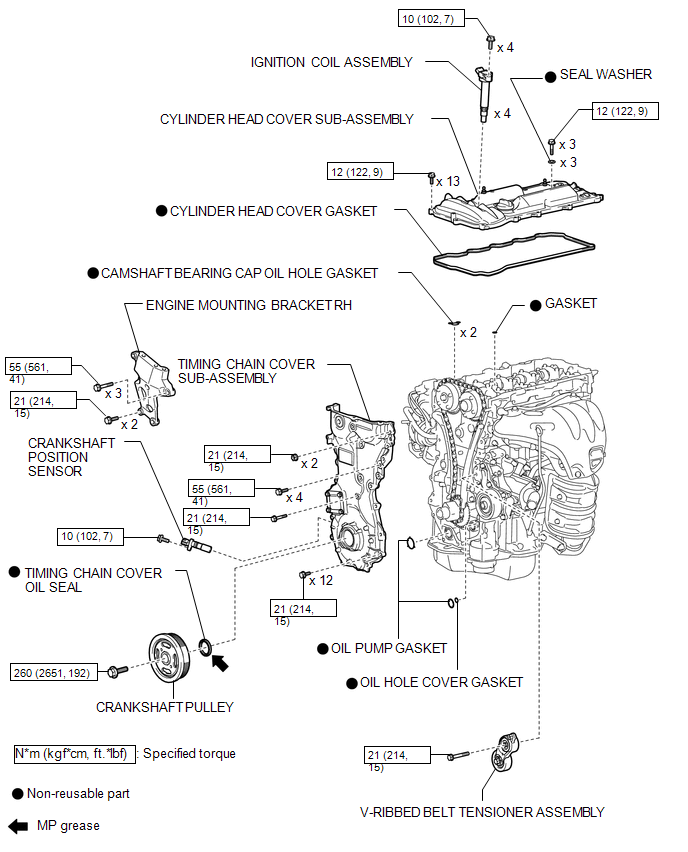
ILLUSTRATION
 Oil Pump
...
 Installation
INSTALLATION
PROCEDURE
1. INSTALL TIMING CHAIN COVER SUB-ASSEMBLY
(a) Apply a light coat of engine oil to 2 new oil pump gaskets and new
oil hole cover gasket.
...
Other materials about Toyota Venza:
Evaporative Emission Control System Leak Detected (Gross Leak) (P0455,P0456)
DTC SUMMARY
DTC No.
Monitoring Item
Malfunction Detection Condition
Trouble Area
Detection Timing
Detection Logic
P0455
EVAP gross leak
Leak detection pum ...
Manual Shifting Test
MANUAL SHIFTING TEST
1. PERFORM MANUAL SHIFTING TEST
HINT:
Using this test, it can be determined whether a problem is in an electrical
circuit or if it is a mechanical problem in the transaxle.
If any abnormalities are found in the following ...
How To Proceed With Troubleshooting
CAUTION / NOTICE / HINT
HINT:
Use the following procedure to troubleshoot the smart key system.
*: Use the Techstream.
PROCEDURE
1.
VEHICLE BROUGHT TO WORKSHOP
NEXT
...

0.1618