Toyota Venza: Components
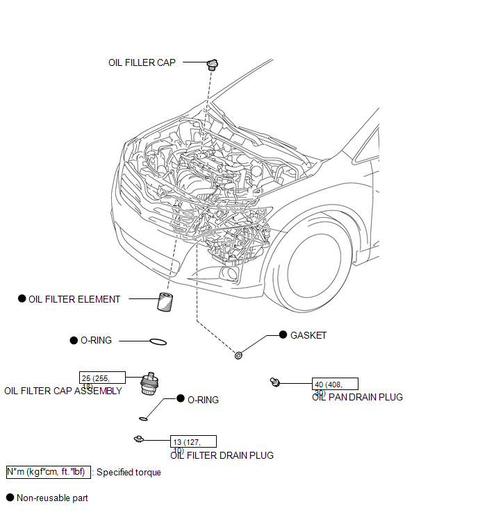
COMPONENTS
ILLUSTRATION

 Replacement
REPLACEMENT
CAUTION / NOTICE / HINT
CAUTION:
Prolonged and repeated contact with engine oil will result in the removal
of natural oils from the skin, leading to dryness, irritation and ...
Other materials about Toyota Venza:
Removal
REMOVAL
PROCEDURE
1. DISCONNECT CABLE FROM NEGATIVE BATTERY TERMINAL
NOTICE:
When disconnecting the cable, some systems need to be initialized after the cable
is reconnected (See page ).
2. REMOVE NO. 1 ENGINE COVER SUB-ASSEMBLY
3. REMOVE COOL AIR ...
Clearance Warning ECU Power Source Circuit
DESCRIPTION
This circuit provides power to operate the clearance warning ECU assembly.
WIRING DIAGRAM
CAUTION / NOTICE / HINT
NOTICE:
Inspect the fuses for circuits related to this system before performing the following
inspection procedure.
PROCEDUR ...
Throttle Actuator Control System - Stuck Open (P2111,P2112)
DESCRIPTION
The throttle actuator is operated by the ECM, and opens and closes the throttle
valve using gears. The opening angle of the throttle valve is detected by the throttle
position sensor, which is mounted on the throttle body. The throttle positio ...

0.1291