Toyota Venza: Brake
General Maintenance
GENERAL MAINTENANCE
PROCEDURE
1. INSPECT BRAKE LINE PIPES AND HOSES
HINT:
Work in a well-lighted area. Turn the front wheels fully to the right or left before beginning the inspection.
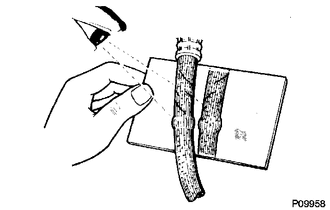
(a) Using a mirror, check the entire circumference and length of the brake lines and hoses for:
- Damage
- Wear
- Deformation
- Cracks
- Corrosion
- Leaks
- Kinks
- Twists
(b) Check all the clamps for tightness and check the connections for leaks.
(c) Check that the hoses and lines are not near sharp edges, moving parts or the exhaust system.
(d) Check that the lines are installed properly and pass through the center of the grommets.
2. INSPECT BRAKE PEDAL
(a) Check the brake pedal (See page .gif) ).
).
3. INSPECT PARKING BRAKE
(a) Check the parking brake shoe clearance and parking brake pedal travel (See
page ).
(b) Check the parking brake cables to ensure that they are not deformed or binding.
4. INSPECT BRAKE LININGS AND DRUMS
(a) Check the parking brake linings and drums.
5. INSPECT FRONT BRAKE
(a) Check the front brake pads and discs (See page
).
6. INSPECT REAR BRAKE
(a) Check the rear brake pads and discs (See page
).
7. INSPECT OR CHANGE BRAKE FLUID
(a) Inspect or change the brake fluid (See page
).
Fluid:
SAE J1703 or FMVSS No. 116 DOT3
 Body
Body
General Maintenance
GENERAL MAINTENANCE
PROCEDURE
1. TIGHTEN BOLTS AND NUTS ON CHASSIS AND BODY
(a) If necessary, tighten the bolts and nuts on the chassis parts listed below.
Front axle ...
 Chassis
General Maintenance
GENERAL MAINTENANCE
PROCEDURE
1. INSPECT STEERING LINKAGE AND GEAR HOUSING
(a) Check the steering wheel free play (See page
).
(b) Check the steering linkage for looseness ...
Other materials about Toyota Venza:
Engine Immobiliser System Malfunction (B2799)
DESCRIPTION
This DTC is stored when one of the following occurs: 1) the ECM detects errors
in its own communications with the transponder key ECU assembly; 2) the ECM detects
errors in the communication lines; or 3) the ECU communication ID between the tr ...
How To Use This Manual
General Information
GENERAL INFORMATION
1. GENERAL DESCRIPTION
(a) This manual is written in accordance with SAE J2008.
(b) Repair operations can be separated mainly into the following 3 processes:
(1) Diagnosis
(2) Removing / Installing, Replacing, Di ...
Removal
REMOVAL
PROCEDURE
1. REMOVE AUTOMATIC TRANSAXLE ASSEMBLY
HINT:
See the steps from "Remove Engine Assembly with transaxle" through "Remove Automatic
Transaxle Assembly" (See page ).
2. REMOVE AUTOMATIC TRANSAXLE OIL PAN SUB-ASSEMBLY
...

0.129