Toyota Venza: Air Conditioning Amplifier
Components
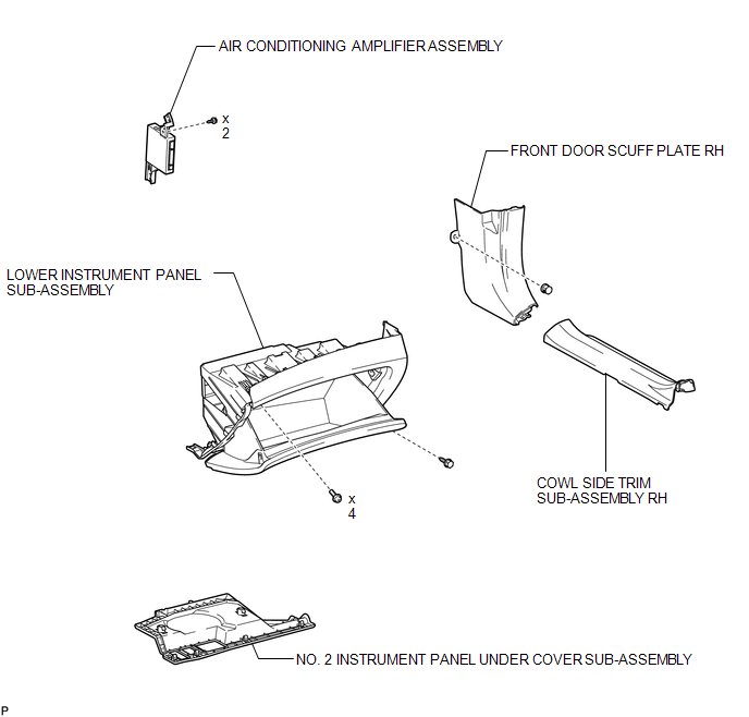
COMPONENTS
ILLUSTRATION
Installation
INSTALLATION
PROCEDURE
1. INSTALL AIR CONDITIONING AMPLIFIER ASSEMBLY
|
(a) Install the air conditioning amplifier assembly with the 2 screws. |
|
(b) Connect each connector.
NOTICE:
Be careful when installing the air conditioning amplifier assembly. If the air conditioning amplifier assembly is dropped, replace it with a new one.
2. INSTALL LOWER INSTRUMENT PANEL SUB-ASSEMBLY
.gif)
3. INSTALL NO. 2 INSTRUMENT PANEL UNDER COVER SUB-ASSEMBLY
4. INSTALL COWL SIDE TRIM SUB-ASSEMBLY RH
HINT:
Use the same procedure for the RH side and the LH side (See page
).
5. INSTALL FRONT DOOR SCUFF PLATE RH
HINT:
Use the same procedure for the RH side and the LH side (See page
).
6. CONNECT CABLE TO NEGATIVE BATTERY TERMINAL
NOTICE:
When disconnecting the cable, some systems need to be initialized after the cable
is reconnected (See page ).
Removal
REMOVAL
PROCEDURE
1. DISCONNECT CABLE FROM NEGATIVE BATTERY TERMINAL
NOTICE:
When disconnecting the cable, some systems need to be initialized after the cable
is reconnected (See page .gif) ).
).
2. REMOVE FRONT DOOR SCUFF PLATE RH
HINT:
Use the same procedure for the RH side and the LH side (See page
).
3. REMOVE COWL SIDE TRIM SUB-ASSEMBLY RH
HINT:
Use the same procedure for the RH side and the LH side (See page
).
4. REMOVE NO. 2 INSTRUMENT PANEL UNDER COVER SUB-ASSEMBLY
5. REMOVE LOWER INSTRUMENT PANEL SUB-ASSEMBLY
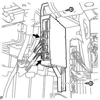
6. REMOVE AIR CONDITIONING AMPLIFIER ASSEMBLY
|
(a) Disconnect each connector. |
|
.png)
(b) Remove the 2 screws and air conditioning amplifier assembly.
NOTICE:
Be careful when removing the air conditioning amplifier assembly. If the air conditioning amplifier assembly is dropped, replace it with a new one.

 Air Conditioning Panel
Components
COMPONENTS
ILLUSTRATION
Installation
INSTALLATION
PROCEDURE
1. INSTALL AIR CONDITIONING CONTROL ASSEMBLY
(a) Connect the connector.
(b) Engage the 2 clips and 4 gui ...
Other materials about Toyota Venza:
Installation
INSTALLATION
CAUTION / NOTICE / HINT
HINT:
Use the same procedure for the RH side and LH side.
The procedure listed below is for the LH side.
PROCEDURE
1. INSTALL REAR AIRBAG SENSOR
(a) Check that the ignition switch is off.
(b) Check ...
Installation
INSTALLATION
PROCEDURE
1. INSTALL INSTRUMENT PANEL WIRE ASSEMBLY
(a) Connect the vent hole connector of the instrument panel wire to the
front passenger airbag assembly.
Text in Illustration
*1
Vent Hol ...
Terminals Of Ecu
TERMINALS OF ECU
1. A/C AMPLIFIER
HINT:
Check from the rear of the connector while it is connected to the A/C amplifier.
Terminal No.
(Symbol)
Wiring Color
Terminal Description
Condition
Specified ...

0.1391