Toyota Venza: Terminals Of Ecu
TERMINALS OF ECU
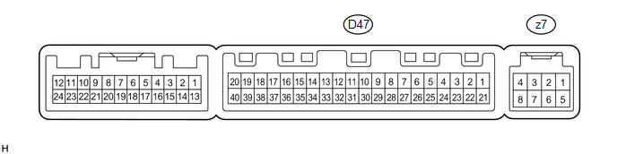
1. A/C AMPLIFIER
HINT:
Check from the rear of the connector while it is connected to the A/C amplifier.
|
Terminal No. (Symbol) |
Wiring Color |
Terminal Description |
Condition |
Specified Condition |
|---|---|---|---|---|
|
D47-1 (IG+) - D47-14 (GND) |
Y - W |
Power source (IG) |
Ignition switch ON |
11 to 14 V |
|
D47-1 (IG+) - D47-14 (GND) |
Y - W |
Power source (IG) |
Ignition switch off |
Below 1 V |
|
D47-2 (SOL+) - D47-14 (GND) |
L - W |
A/C compressor solenoid operation signal |
Engine running A/C switch: on Blower switch: LO |
Pulse generation (See waveform 1) |
|
D47-5 (TAM) - D47-13 (GND) |
V - L |
Ambient temperature sensor signal |
Ignition switch ON Ambient temperature: 25°C (77°F) |
1.35 to 1.75 V |
|
D47-5 (TAM) - D47-13 (GND) |
V - L |
Ambient temperature sensor signal |
Ignition switch ON Ambient temperature: 40°C (104°F) |
0.9 to 1.2 V |
|
D47-8 (LOCK) - D47-13 (GND)*1 |
P - L |
A/C compressor lock sensor signal |
Engine running Blower switch: LO A/C switch: on |
Pulse generation (See waveform 2) |
|
D47-9 (PRE) - D47-13 (GND) |
R - L |
A/C pressure sensor signal |
Start engine, Operate A/C system, Refrigerant pressure: Abnormal pressure (more than 3140 kPa (32.0 kgf/cm2, 455 psi)) |
4.84 V or higher |
|
D47-9 (PRE) - D47-13 (GND) |
R - L |
A/C pressure sensor signal |
Start engine, Operate A/C system, Refrigerant pressure: Abnormal pressure (less than 196 kPa (2.0 kgf/cm2, 28 psi)) |
Below 0.73 V |
|
D47-9 (PRE) - D47-13 (GND) |
R - L |
A/C pressure sensor signal |
Start engine, Operate A/C system, Refrigerant pressure: Normal pressure (less than 3140 kPa (32.0 kgf/cm2, 455 psi) and more than 196 kPa (2.0 kgf/cm2, 28 psi)) |
0.73 to 4.84 V |
|
D47-10 (S5-3) - D47-13 (GND) |
P - L |
Power supply for A/C pressure sensor |
Ignition switch ON A/C switch: on |
4.75 to 5.25 V |
|
D47-10 (S5-3) - D47-13 (GND) |
P - L |
Power supply for A/C pressure sensor |
Ignition switch ON A/C switch: off |
Below 1 V |
|
D47-11 (CANH) - D47-12 (CANL) |
P - W |
CAN communication system |
CAN communication circuit |
Pulse generation |
|
D47-13 (GND) - Body ground |
L - Body ground |
Ground for A/C pressure sensor, A/C ambient temperature sensor, A/C lock sensor |
Always |
Below 1 V |
|
D47-14 (GND) - Body ground |
W - Body ground |
Ground for main power supply |
Always |
Below 1 V |
|
D47-18 (D) - D47-14 (GND) |
G - W |
DEF relay signal |
Ignition switch ON REAR DEF switch: on |
Below 1 V |
|
D47-18 (D) - D47-14 (GND) |
G - W |
DEF relay signal |
Ignition switch ON REAR DEF switch: off |
11 to 14 V |
|
D47-20 (MGC) - D47-14 (GND)*1 |
Y - W |
A/C compressor magnetic clutch operation signal |
Ignition switch ON Blower switch: LO A/C switch: off |
11 to 14 V |
|
D47-20 (MGC) - D47-14 (GND)*1 |
Y - W |
A/C compressor magnetic clutch operation signal |
Ignition switch ON Blower switch: LO A/C switch: on |
Below 1 V |
|
D47-21 (B) - D47-14 (GND) |
V - W |
Power source (Back-up) |
Always |
11 to 14 V |
|
D47-23 (BLW) - D47-14 (GND) |
R - W |
Blower motor speed control signal |
Ignition switch ON Blower switch: LO |
Pulse generation (See waveform 3) |
|
D47-29 (TR) - D47-34 (SG-1) |
LG - V |
Room temperature sensor signal |
Ignition switch ON Cabin temperature: 25°C (77°F) |
1.8 to 2.2 V |
|
D47-29 (TR) - D47-34 (SG-1) |
LG - V |
Room temperature sensor signal |
Ignition switch ON Cabin temperature: 40°C (104°F) |
1.2 to 1.6 V |
|
D47-32 (TSP) - D47-14 (GND) |
LG - W |
Solar sensor signal (for Front passenger side) |
Ignition switch ON Solar sensor subjected to electric light |
0.8 to 4.3 V |
|
D47-32 (TSP) - D47-14 (GND) |
LG - W |
Solar sensor signal (for Front passenger side) |
Ignition switch ON Solar sensor covered with a cloth |
Below 0.8 V |
|
D47-33 (TSD) - D47-14 (GND) |
P - W |
Solar sensor signal (for Driver side) |
Ignition switch ON Solar sensor subjected to electric light |
0.8 to 4.3 V |
|
D47-33 (TSD) - D47-14 (GND) |
P - W |
Solar sensor signal (for Driver side) |
Ignition switch ON Solar sensor covered with a cloth |
Below 0.8 V |
|
D47-34 (SG-1) - Body ground |
V - Body ground |
Ground for room temperature sensor |
Always |
Below 1 V |
|
D47-37 (LIN1) - D47-14 (GND) |
SB - W |
LIN communication signal |
Ignition switch ON |
Pulse generation |
|
z7-2 (BUS G) - Body ground |
- |
Ground for BUS IC |
Always |
Below 1 V |
|
z7-3 (BUS) - z7-2 (BUS G) |
- |
BUS IC control signal |
Ignition switch ON |
Pulse generation |
|
z7-4 (B BUS) - z7-2 (BUS G) |
- |
Power supply for BUS IC |
Ignition switch off |
Below 1 V |
|
z7-4 (B BUS) - z7-2 (BUS G) |
- |
Power supply for BUS IC |
Ignition switch ON |
11 to 14 V |
|
z7-5 (SGA) - Body ground |
- |
Ground for evaporator temperature sensor |
Always |
Below 1 V |
|
z7-6 (TEA) - z7-5 (SGA) |
- |
A/C evaporator temperature sensor signal |
Ignition switch ON Evaporator temperature: 0°C (32°F) |
1.7 to 2.1 V |
|
z7-6 (TEA) - z7-5 (SGA) |
- |
A/C evaporator temperature sensor signal |
Ignition switch ON Evaporator temperature: 15°C (59°F) |
0.9 to 1.3 V |
- *1: for 2GR-FE
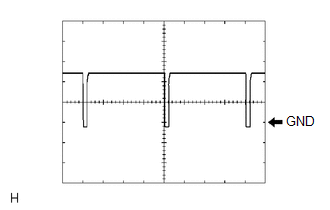
(a) Waveform 1:
|
Item |
Content |
|---|---|
|
Terminal No. |
D47-2 (SOL+) - D47-14 (GND) |
|
Tool Setting |
5 V/DIV., 500 μs/DIV. |
|
Vehicle Condition |
Engine running A/C switch: on |
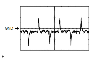
(b) Waveform 2:
|
Item |
Content |
|---|---|
|
Terminal No. |
D47-8 (LOCK) - D47-13 (GND) |
|
Tool Setting |
200 mV/DIV., 10 ms./DIV. |
|
Vehicle Condition |
Engine running Blower switch: LO A/C switch: on |
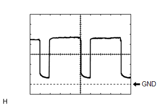
(c) Waveform 3:
|
Item |
Content |
|---|---|
|
Terminal No. |
D47-23 (BLW) - D47-14 (GND) |
|
Tool Setting |
1 V/DIV., 500 μs/DIV. |
|
Vehicle Condition |
Ignition switch ON Blower switch: LO |
2. AIR CONDITIONING CONTROL ASSEMBLY

HINT:
Check from the rear of the connector while it is connected to the air conditioning control assembly.
|
Terminal No. (Symbol) |
Wiring Color |
Terminal Description |
Condition |
Specified Condition |
|---|---|---|---|---|
|
E3-1 (ILL-) - E3-3 (ILL+) |
L - BR |
Light control switch signal |
Light control switch: OFF |
Below 1 V |
|
E3-1 (ILL-) - E3-3 (ILL+) |
L - BR |
Light control switch signal |
Light control switch: TAIL |
11 to 14 V |
|
E3-2 (LIN1) - E3-5 (GND) |
SB - W |
LIN communication signal |
Ignition switch ON |
Pulse generation |
|
E3-4 (IG+) - E3-5 (GND) |
GR - W |
Power source (IG) |
Ignition switch off |
Below 1 V |
|
E3-4 (IG+) - E3-5 (GND) |
GR - W |
Power source (IG) |
Ignition switch ON |
11 to 14 V |
|
E3-5 (GND) - Body ground |
W - Body ground |
Ground for front air conditioning control assembly |
Always |
Below 1 V |
 Problem Symptoms Table
PROBLEM SYMPTOMS TABLE
HINT:
Use the table below to help determine the cause of problem symptoms.
If multiple suspected areas are listed, the potential causes of the symptoms
are lis ...
 Diagnosis System
DIAGNOSIS SYSTEM
1. DESCRIPTION
(a) Air conditioning system data and the Diagnostic Trouble Codes (DTCs) can
be read through the Data Link Connector 3 (DLC3) of the vehicle. When the system
seem ...
Other materials about Toyota Venza:
Utility vehicle feature
• Specific design characteristics give it a higher center of gravity than ordinary
passenger cars. This vehicle design feature causes this type of vehicle to be more
likely to rollover. And, utility vehicles have a significantly higher rollover rate
th ...
Clearance Warning Buzzer Circuit
DESCRIPTION
This circuit consists of the No. 1 clearance warning buzzer and clearance warning
ECU assembly. An ECU-excited type buzzer is used. The ECU operates the buzzer using
a sound pattern that changes depending on the distance to the obstacle.
WIRI ...
Installation
INSTALLATION
CAUTION / NOTICE / HINT
HINT:
When installing the mouldings, heat the vehicle body and mouldings using a heat
light.
Heating Temperature
Item
Temperature
Vehicle Body
40 to 60°C (104 to 140 ...

0.119