Toyota Venza: Check CAN Bus Lines for Short Circuit
DESCRIPTION
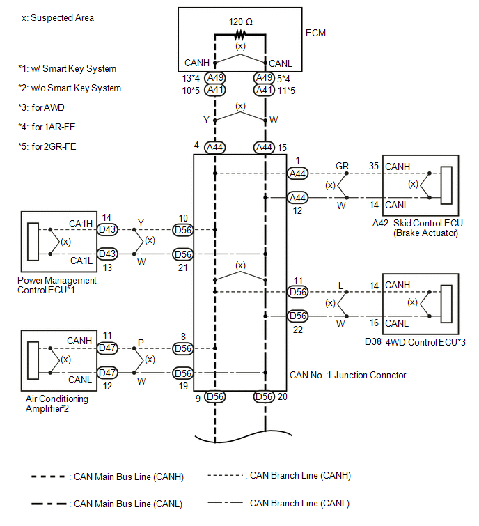
There may be a short circuit in the CAN bus main wire and/or CAN branch wire
when the resistance between terminals 6 (CANH) and 14 (CANL) of the DLC3 is below
54 Ω.
|
Symptom
|
Trouble Area
|
|
Resistance between terminals 6 (CANH) and 14 (CANL) of DLC3 is below
54 Ω.
|
- Short in CAN bus main wire
- Short in CAN bus branch wire
- Combination meter
- ECM
- Power steering ECU
- Center airbag sensor assembly
- Air conditioning amplifier*3
- Skid control ECU (Brake actuator)
- Steering angle sensor
- Yaw rate sensor
- Main body ECU (Driver side junction block)
- 4WD control ECU*1
- Certification ECU*2
- Power management control ECU*2
- Navigation receiver assembly*4
- Radio and display receiver assembly*5
- CAN No. 1 junction connector
- CAN No. 2 junction connector
|
*1: for AWD
*2: w/ Smart key system
*3: w/o Smart key system
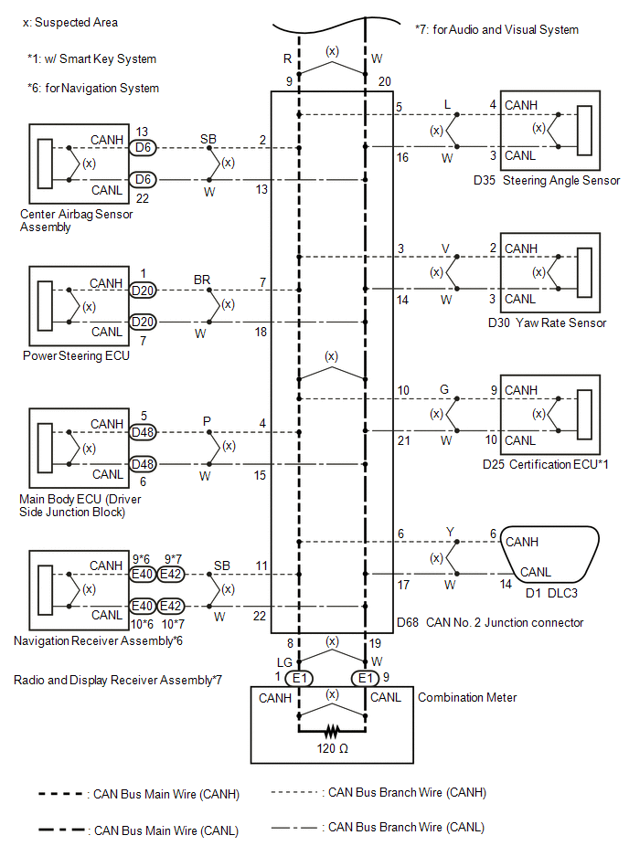
*4: for Navigation system
*5: for Audio and visual system
WIRING DIAGRAM
CAUTION / NOTICE / HINT
NOTICE:
- Turn the ignition switch off before measuring the resistances between
CAN bus main wires and between CAN bus branch wires.
- Turn the ignition switch off before inspecting CAN bus wires for a ground
short.
- After the ignition switch is turned off, check that the key reminder
warning system and light reminder warning system are not operating.
- Before measuring the resistance, leave the vehicle as is for at least
1 minute and do not operate the ignition switch, any other switches or the
doors. If any doors need to be opened in order to check connectors, open
the doors and leave them open.
HINT:
- Operating the ignition switch, any other switches or a door triggers
related ECU and sensor communication on the CAN. This communication will
cause the resistance value to change.
- Even after DTCs are cleared, if a DTC is stored again after driving
the vehicle for a while, the malfunction may be occurring due to vibration
of the vehicle. In such a case, wiggling the ECUs or wire harness while
performing the inspection below may help determine the cause of the malfunction.
PROCEDURE
|
1.
|
CHECK FOR SHORT IN CAN BUS WIRES (CAN NO. 1 J/C - CAN NO. 2 J/C)
|
(a) Turn the ignition switch off.
|
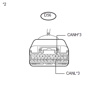
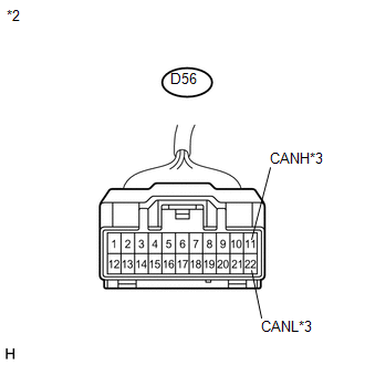
(b) Disconnect the CAN No. 1 junction connector (D56).
Text in Illustration
|
*1
|
Front view of wire harness connector
(to CAN No. 1 Junction Connector)
|
|
*2
|
to CAN No. 2 Junction Connector
|
|
|
(c) Measure the resistance according to the value(s) in the table below.
Standard Resistance:
|
Tester Connection
|
Condition
|
Specified Condition
|
|
D56-9 (CANH) - D56-20 (CANL)
|
Ignition switch off
|
108 to 132 Ω
|
| NG |
.gif) |
GO TO STEP 12
|
| OK |
.gif) |
|
|
2.
|
CHECK FOR SHORT IN CAN BUS WIRES (CAN NO. 1 J/C - ECM)
|
|
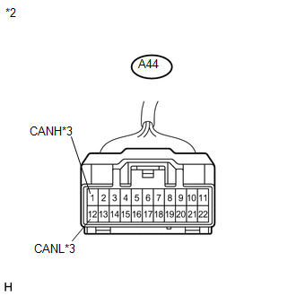
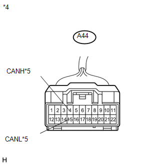
(a) Disconnect the CAN No. 1 junction connector (A44).
Text in Illustration
|
*1
|
Front view of wire harness connector
(to CAN No. 1 Junction Connector)
|
|
*2
|
to ECM
|
|
|
(b) Measure the resistance according to the value(s) in the table below.
Standard Resistance:
|
Tester Connection
|
Condition
|
Specified Condition
|
|
A44-4 (CANH) - A44-15 (CANL)
|
Ignition switch off
|
108 to 132 Ω
|
| NG |
|
GO TO STEP 11
|
| OK |
|
|
|
|
3.
|
CHECK FOR SHORT IN CAN BUS WIRES (CAN NO. 1 J/C - SKID CONTROL ECU)
|
|
(a) Disconnect the skid control ECU connector.
Text in Illustration
|
*1
|
Front view of wire harness connector
(to Skid Control ECU)
|
|
|
|
(b) Measure the resistance according to the value(s) in the table below.
Standard Resistance:
|
Tester Connection
|
Condition
|
Specified Condition
|
|
A44-1 (CANH) - A44-12 (CANL)
|
Ignition switch off
|
1 MΩ or higher
|
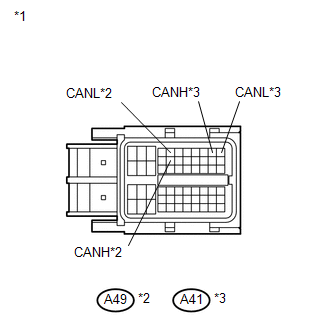
Text in Illustration
|
*2
|
Front view of wire harness connector
(to CAN No. 1 Junction Connector)
|
|
*3
|
to Skid Control ECU
|
|
|
| NG |
|
REPAIR OR REPLACE CAN BUS BRANCH WIRE OR CONNECTOR (CAN NO. 1 J/C - SKID
CONTROL ECU)
|
| OK |
|
|
|
|
4.
|
CHECK FOR SHORT IN CAN BUS WIRES (CAN NO. 1 J/C - AIR CONDITIONING AMPLIFIER)
|
HINT:
For vehicles with smart key system, go to the next step.
|
(a) Disconnect the air conditioning amplifier connector.
Text in Illustration
|
*1
|
Front view of wire harness connector
(to Air Conditioning Amplifier)
|
|
|
|
(b) Measure the resistance according to the value(s) in the table below.
Standard Resistance:
|
Tester Connection
|
Condition
|
Specified Condition
|
|
D56-8 (CANH) - D56-19 (CANL)
|
Ignition switch off
|
1 MΩ or higher
|
Text in Illustration
|
*2
|
Front view of wire harness connector
(to CAN No. 1 Junction Connector)
|
|
*3
|
to Air Conditioning Amplifier
|
|
|
| NG |
|
REPAIR OR REPLACE CAN BUS BRANCH WIRE OR CONNECTOR (CAN NO. 1 J/C - AIR
CONDITIONING AMPLIFIER)
|
| OK |
|
|
|
|
5.
|
CHECK FOR SHORT IN CAN BUS WIRES (CAN NO. 1 J/C - 4WD CONTROL ECU)
|
HINT:
For 2WD vehicles, go to the next step.
|
(a) Disconnect the 4WD control ECU connector.
Text in Illustration
|
*1
|
Front view of wire harness connector
(to 4WD Control ECU)
|
|
|
|
(b) Measure the resistance according to the value(s) in the table below.
Standard Resistance:
|
Tester Connection
|
Condition
|
Specified Condition
|
|
D56-11 (CANH) - D56-22 (CANL)
|
Ignition switch off
|
1 MΩ or higher
|
Text in Illustration
|
*2
|
Front view of wire harness connector
(to CAN No. 1 Junction Connector)
|
|
*3
|
to 4WD Control ECU
|
|
|
| NG |
|
REPAIR OR REPLACE CAN BUS BRANCH WIRE OR CONNECTOR (CAN NO. 1 J/C - 4WD
CONTROL ECU)
|
| OK |
|
|
|
|
6.
|
CHECK FOR SHORT IN CAN BUS WIRES (CAN NO. 1 J/C - POWER MANAGEMENT CONTROL
ECU)
|
HINT:
For vehicles without smart key system, go to the next step.
|
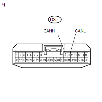
(a) Disconnect the power management control ECU connector (D43).
Text in Illustration
|
*1
|
Rear view of wire harness connector
(to Power Management Control ECU)
|
|
|
|
(b) Measure the resistance according to the value(s) in the table below.
Standard Resistance:
|
Tester Connection
|
Condition
|
Specified Condition
|
|
D56-10 (CANH) - D56-21 (CANL)
|
Ignition switch off
|
1 MΩ or higher
|
Text in Illustration
|
*2
|
Front view of wire harness connector
(to CAN No. 1 Junction Connector)
|
|
*3
|
to Power Management Control ECU
|
|
|
| NG |
|
REPAIR OR REPLACE CAN BUS BRANCH WIRE OR CONNECTOR (CAN NO. 1 J/C - POWER
MANAGEMENT CONTROL ECU)
|
| OK |
|
|
|
|
7.
|
CHECK FOR SHORT IN CAN BUS WIRES (CAN NO. 1 J/C)
|
(a) Reconnect the CAN No. 1 junction connector (A44).
(b) Reconnect the CAN No. 1 junction connector (D56).
|
(c) Measure the resistance according to the value(s) in the table below.
Text in Illustration
NOTICE:
The resistance must be measured after the main wire connected ECUs (ECM
and combination meter), and CAN No. 1 and No. 2 junction connectors are
reconnected.
Standard Resistance:
|
Tester Connection
|
Condition
|
Specified Condition
|
|
D1-6 (CANH) - D1-14 (CANL)
|
Ignition switch off
|
54 to 69 Ω
|
|
|
| NG |
|
REPLACE CAN NO. 1 J/C
|
| OK |
|
|
|
|
8.
|
CHECK FOR SHORT IN CAN BUS WIRES (SKID CONTROL ECU)
|
(a) Reconnect the skid control ECU connector.
|
(b) Measure the resistance according to the value(s) in the table below.
Standard Resistance:
|
Tester Connection
|
Condition
|
Specified Condition
|
|
D1-6 (CANH) - D1-14 (CANL)
|
Ignition switch off
|
54 to 69 Ω
|
Text in Illustration
|
|
|
Result
|
Proceed to
|
|
OK (for AWD and w/o Smart key system)
|
A
|
|
OK (for 2WD and w/o Smart key system)
|
B
|
|
OK (for AWD and w/ Smart key system)
|
C
|
|
OK (for 2WD and w/ Smart key system)
|
D
|
|
NG
|
E
|
| B |
|
REPLACE AIR CONDITIONING AMPLIFIER
|
| C |
|
GO TO STEP 10
|
| D |
|
REPLACE POWER MANAGEMENT CONTROL ECU
|
| E |
|
REPLACE BRAKE ACTUATOR (SKID CONTROL ECU)
|
| A |
|
|
|
|
9.
|
CHECK FOR SHORT IN CAN BUS WIRES (AIR CONDITIONING AMPLIFIER)
|
(a) Reconnect the air conditioning amplifier connector.
|
(b) Measure the resistance according to the value(s) in the table below.
Standard Resistance:
|
Tester Connection
|
Condition
|
Specified Condition
|
|
D1-6 (CANH) - D1-14 (CANL)
|
Ignition switch off
|
54 to 69 Ω
|
Text in Illustration
|
|
| OK |
|
REPLACE 4WD CONTROL ECU
|
| NG |
|
REPLACE AIR CONDITIONING AMPLIFIER
|
|
10.
|
CHECK FOR SHORT IN CAN BUS WIRES (POWER MANAGEMENT CONTROL ECU)
|
(a) Reconnect the power management control ECU connector.
|
(b) Measure the resistance according to the value(s) in the table below.
Standard Resistance:
|
Tester Connection
|
Condition
|
Specified Condition
|
|
D1-6 (CANH) - D1-14 (CANL)
|
Ignition switch off
|
54 to 69 Ω
|
Text in Illustration
|
|
| OK |
|
REPLACE 4WD CONTROL ECU
|
| NG |
|
REPLACE POWER MANAGEMENT CONTROL ECU
|
|
11.
|
CHECK FOR SHORT IN CAN BUS WIRES (ECM)
|
|
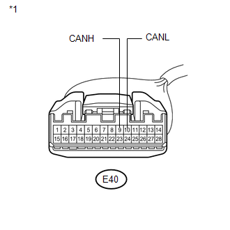
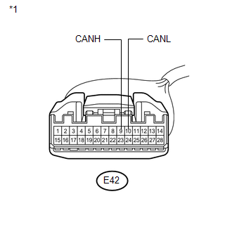
(a) Disconnect the ECM connector.
Text in Illustration
|
*1
|
Front view of wire harness connector
(to ECM)
|
|
*2
|
for 1AR-FE
|
|
*3
|
for 2GR-FE
|
|
|
|
(b) Measure the resistance according to the value(s) in the table below.
Standard Resistance:
|
Tester Connection
|
Condition
|
Specified Condition
|
|
A44-4 (CANH) - A44-15 (CANL)
|
Ignition switch off
|
1 MΩ or higher
|
Text in Illustration
|
*4
|
Front view of wire harness connector
(to CAN No. 1 Junction Connector)
|
|
*5
|
to ECM
|
|
|
|
Result
|
Proceed to
|
|
OK (for 1AR-FE)
|
A
|
|
OK (for 2GR-FE)
|
B
|
|
NG
|
C
|
| A |
|
REPLACE ECM
|
| B |
|
REPLACE ECM
|
| C |
|
REPAIR OR REPLACE CAN BUS MAIN WIRE OR CONNECTOR (CAN NO. 1 J/C - ECM)
|
|
12.
|
CHECK FOR SHORT IN CAN BUS WIRES (CAN NO. 2 J/C - CAN NO. 1 J/C)
|
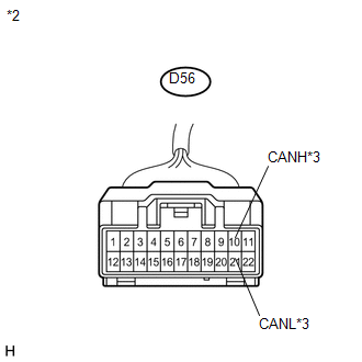
(a) Reconnect the CAN No. 1 junction connector (D56).
|
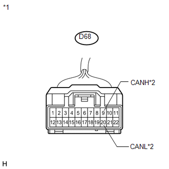
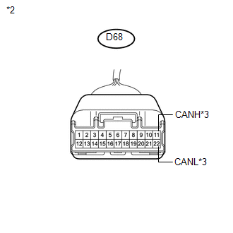
(b) Disconnect the CAN No. 2 junction connector.
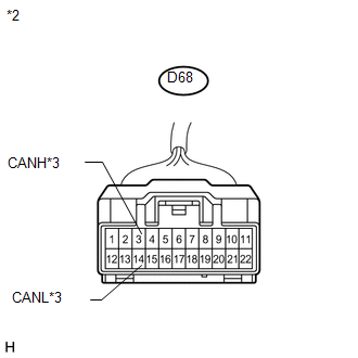
Text in Illustration
|
*1
|
Front view of wire harness connector
(to CAN No. 2 Junction Connector)
|
|
*2
|
to CAN No. 1 Junction Connector
|
|
|
(c) Measure the resistance according to the value(s) in the table below.
Standard Resistance:
|
Tester Connection
|
Condition
|
Specified Condition
|
|
D68-9 (CANH) - D68-20 (CANL)
|
Ignition switch off
|
108 to 132 Ω
|
| NG |
|
REPAIR OR REPLACE CAN BUS MAIN WIRE OR CONNECTOR (CAN NO. 1 J/C - CAN
NO. 2 J/C)
|
| OK |
|
|
|
|
13.
|
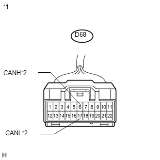
CHECK FOR SHORT IN CAN BUS WIRES (CAN NO. 2 J/C - DLC3)
|
|
(a) Measure the resistance according to the value(s) in the table below.
Standard Resistance:
|
Tester Connection
|
Condition
|
Specified Condition
|
|
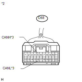
D68-6 (CANH) - D68-17 (CANL)
|
Ignition switch off
|
1 MΩ or higher
|
Text in Illustration
|
*1
|
Front view of wire harness connector
(to CAN No. 2 Junction Connector)
|
|
*2
|
to DLC3
|
|
|
| NG |
|
REPAIR OR REPLACE CAN BRANCH WIRE CONNECTED TO DLC3
|
| OK |
|
|
|
|
14.
|
CHECK FOR SHORT IN CAN BUS WIRES (CAN NO. 2 J/C - COMBINATION METER)
|
|
(a) Measure the resistance according to the value(s) in the table below.
Standard Resistance:
|
Tester Connection
|
Condition
|
Specified Condition
|
|
D68-8 (CANH) - D68-19 (CANL)
|
Ignition switch off
|
108 to 132 Ω
|
Text in Illustration
|
*1
|
Front view of wire harness connector
(to CAN No. 2 Junction Connector)
|
|
*2
|
to Combination Meter
|
|
|
| NG |
|
GO TO STEP 31
|
| OK |
|
|
|
|
15.
|
CHECK FOR SHORT IN CAN BUS WIRES (CAN NO. 2 J/C - CENTER AIRBAG SENSOR
ASSEMBLY)
|
|
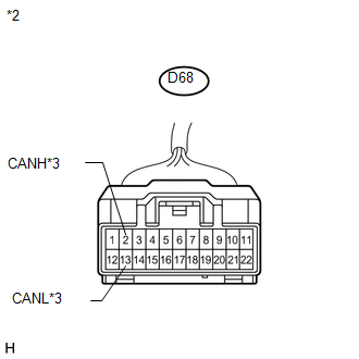
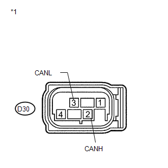
(a) Disconnect the center airbag sensor assembly connector (D6).
Text in Illustration
|
*1
|
Front view of wire harness connector
(to Center Airbag Sensor Assembly)
|
|
|
|
(b) Measure the resistance according to the value(s) in the table below.
Standard Resistance:
|
Tester Connection
|
Condition
|
Specified Condition
|
|
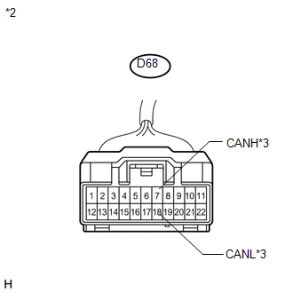
D68-2 (CANH) - D68-13 (CANL)
|
Ignition switch off
|
1 MΩ or higher
|
Text in Illustration
|
*2
|
Front view of wire harness connector
(to CAN No. 2 Junction Connector)
|
|
*3
|
to Center Airbag Sensor Assembly
|
|
|
| NG |
|
REPAIR OR REPLACE CAN BUS BRANCH WIRE OR CONNECTOR (CAN NO. 2 J/C - CENTER
AIRBAG SENSOR ASSEMBLY)
|
| OK |
|
|
|
|
16.
|
CHECK FOR SHORT IN CAN BUS WIRES (CAN NO. 2 J/C - YAW RATE SENSOR)
|
|
(a) Disconnect the yaw rate sensor connector.
Text in Illustration
|
*1
|
Front view of wire harness connector
(to Yaw Rate Sensor)
|
|
|
|
(b) Measure the resistance according to the value(s) in the table below.
Standard Resistance:
|
Tester Connection
|
Condition
|
Specified Condition
|
|
D68-3 (CANH) - D68-14 (CANL)
|
Ignition switch off
|
1 MΩ or higher
|
Text in Illustration
|
*2
|
Front view of wire harness connector
(to CAN No. 2 Junction Connector)
|
|
*3
|
to Yaw Rate Sensor
|
|
|
| NG |
|
REPAIR OR REPLACE CAN BUS BRANCH WIRE OR CONNECTOR (CAN NO. 2 J/C - YAW
RATE SENSOR)
|
| OK |
|
|
|
|
17.
|
CHECK FOR SHORT IN CAN BUS WIRES (CAN NO. 2 J/C - STEERING ANGLE SENSOR)
|
|
(a) Disconnect the steering angle sensor connector.
Text in Illustration
|
*1
|
Front view of wire harness connector
(to Steering Angle Sensor)
|
|
|
|
(b) Measure the resistance according to the value(s) in the table below.
Standard Resistance:
|
Tester Connection
|
Condition
|
Specified Condition
|
|
D68-5 (CANH) - D68-16 (CANL)
|
Ignition switch off
|
1 MΩ or higher
|
Text in Illustration
|
*2
|
Front view of wire harness connector
(to CAN No. 2 Junction Connector)
|
|
*3
|
to Steering Angle Sensor
|
|
|
| NG |
|
REPAIR OR REPLACE CAN BUS BRANCH WIRE OR CONNECTOR (CAN NO. 2 J/C - STEERING
ANGLE SENSOR)
|
| OK |
|
|
|
|
18.
|
CHECK FOR SHORT IN CAN BUS WIRES (CAN NO. 2 J/C - POWER STEERING ECU)
|
|
(a) Disconnect the power steering ECU connector (D20).
Text in Illustration
|
*1
|
Front view of wire harness connector
(to Power Steering ECU)
|
|
|
|
(b) Measure the resistance according to the value(s) in the table below.
Standard Resistance:
|
Tester Connection
|
Condition
|
Specified Condition
|
|
D68-7 (CANH) - D68-18 (CANL)
|
Ignition switch off
|
1 MΩ or higher
|
|
|
Text in Illustration
|
*2
|
Front view of wire harness connector
(to CAN No. 2 Junction Connector)
|
|
*3
|
to Power Steering ECU
|
| NG |
|
REPAIR OR REPLACE CAN BUS BRANCH WIRE OR CONNECTOR (CAN NO. 2 J/C - POWER
STEERING ECU)
|
| OK |
|
|
|
|
19.
|
CHECK FOR SHORT IN CAN BUS WIRES (CAN NO. 2 J/C - MAIN BODY ECU)
|
|
(a) Disconnect the main body ECU connector (D48).
Text in Illustration
|
*1
|
Front view of wire harness connector
(to Main Body ECU)
|
|
|
|
(b) Measure the resistance according to the value(s) in the table below.
Standard Resistance:
|
Tester Connection
|
Condition
|
Specified Condition
|
|
D68-4 (CANH) - D68-15 (CANL)
|
Ignition switch off
|
1 MΩ or higher
|
Text in Illustration
|
*2
|
Front view of wire harness connector
(to CAN No. 2 Junction Connector)
|
|
*3
|
to Main Body ECU
|
|
|
|
Result
|
Proceed to
|
|
OK (w/ Smart key system)
|
A
|
|
OK (w/o Smart key system)
|
B
|
|
NG
|
C
|
| B |
|
GO TO STEP 21
|
| C |
|
REPAIR OR REPLACE CAN BUS BRANCH WIRE OR CONNECTOR (CAN NO. 2 J/C - MAIN
BODY ECU)
|
| A |
|
|
|
|
20.
|
CHECK FOR SHORT IN CAN BUS WIRES (CAN NO. 2 J/C - CERTIFICATION ECU)
|
|
(a) Disconnect the certification ECU connector.
Text in Illustration
|
*1
|
Front view of wire harness connector
(to Certification ECU)
|
|
|
|
(b) Measure the resistance according to the value(s) in the table below.
Standard Resistance:
|
Tester Connection
|
Condition
|
Specified Condition
|
|
D68-10 (CANH) - D68-21 (CANL)
|
Ignition switch off
|
1 MΩ or higher
|
Text in Illustration
|
*2
|
Front view of wire harness connector
(to CAN No. 2 Junction Connector)
|
|
*3
|
to Certification ECU
|
|
|
| NG |
|
REPAIR OR REPLACE CAN BUS BRANCH WIRE OR CONNECTOR (CAN NO. 2 J/C - CERTIFICATION
ECU)
|
| OK |
|
|
|
|
21.
|
CHECK FOR SHORT IN CAN BUS WIRES (CAN NO. 2 J/C - NAVIGATION RECEIVER
ASSEMBLY)
|
HINT:
For vehicles without navigation system, go to the next step.
|
(a) Disconnect the navigation receiver assembly connector.
Text in Illustration
|
*1
|
Front view of wire harness connector
(to Navigation Receiver Assembly)
|
|
|
|
(b) Measure the resistance according to the value(s) in the table below.
Standard Resistance:
|
Tester Connection
|
Condition
|
Specified Condition
|
|
D68-11 (CANH) - D68-22 (CANL)
|
Ignition switch off
|
1 MΩ or higher
|
Text in Illustration
|
*2
|
Front view of wire harness connector
(to CAN No. 2 Junction Connector)
|
|
*3
|
to Navigation Receiver Assembly
|
|
|
| NG |
|
REPAIR OR REPLACE CAN BUS BRANCH WIRE OR CONNECTOR (CAN NO. 2 J/C - NAVIGATION
RECEIVER ASSEMBLY)
|
| OK |
|
|
|
|
22.
|
CHECK FOR SHORT IN CAN BUS WIRES (CAN NO. 2 J/C - RADIO AND DISPLAY RECEIVER
ASSEMBLY)
|
HINT:
For vehicles without audio and visual system, go to the next step.
|
(a) Disconnect the radio and display receiver assembly connector.
Text in Illustration
|
*1
|
Front view of wire harness connector
(to Radio and Display Receiver Assembly)
|
|
|
|
(b) Measure the resistance according to the value(s) in the table below.
Standard Resistance:
|
Tester Connection
|
Condition
|
Specified Condition
|
|
D68-11 (CANH) - D68-22 (CANL)
|
Ignition switch off
|
1 MΩ or higher
|
Text in Illustration
|
*2
|
Front view of wire harness connector
(to CAN No. 2 Junction Connector)
|
|
*3
|
to Radio and Display Receiver Assembly
|
|
|
| NG |
|
REPAIR OR REPLACE CAN BUS BRANCH WIRE OR CONNECTOR (CAN NO. 2 J/C - RADIO
AND DISPLAY RECEIVER ASSEMBLY)
|
| OK |
|
|
|
|
23.
|
CHECK FOR SHORT IN CAN BUS WIRES (CAN NO. 2 J/C)
|
(a) Reconnect the CAN No. 2 junction connector.
|
(b) Measure the resistance according to the value(s) in the table below.
NOTICE:
The resistance must be measured after the main wire connected ECUs (ECM
and combination meter), and CAN No. 1 and No. 2 junction connectors are
reconnected.
Standard Resistance:
|
Tester Connection
|
Condition
|
Specified Condition
|
|
D1-6 (CANH) - D1-14 (CANL)
|
Ignition switch off
|
54 to 69 Ω
|
Text in Illustration
|
|
| NG |
|
REPLACE CAN NO. 2 J/C
|
| OK |
|
|
|
|
24.
|
CHECK FOR SHORT IN CAN BUS WIRES (CENTER AIRBAG SENSOR ASSEMBLY)
|
(a) Reconnect the center airbag sensor assembly connector.
|
(b) Measure the resistance according to the value(s) in the table below.
Standard Resistance:
|
Tester Connection
|
Condition
|
Specified Condition
|
|
D1-6 (CANH) - D1-14 (CANL)
|
Ignition switch off
|
54 to 69 Ω
|
Text in Illustration
|
|
| NG |
|
REPLACE CENTER AIRBAG SENSOR ASSEMBLY
|
| OK |
|
|
|
|
25.
|
CHECK FOR SHORT IN CAN BUS WIRES (YAW RATE SENSOR)
|
(a) Reconnect the yaw rate sensor connector.
|
(b) Measure the resistance according to the value(s) in the table below.
Standard Resistance:
|
Tester Connection
|
Condition
|
Specified Condition
|
|
D1-6 (CANH) - D1-14 (CANL)
|
Ignition switch off
|
54 to 69 Ω
|
Text in Illustration
|
|
| NG |
|
REPLACE YAW RATE SENSOR
|
| OK |
|
|
|
|
26.
|
CHECK FOR SHORT IN CAN BUS WIRES (STEERING ANGLE SENSOR)
|
(a) Reconnect the steering angle sensor connector.
|
(b) Measure the resistance according to the value(s) in the table below.
Standard Resistance:
|
Tester Connection
|
Condition
|
Specified Condition
|
|
D1-6 (CANH) - D1-14 (CANL)
|
Ignition switch off
|
54 to 69 Ω
|
|
|
Text in Illustration
| NG |
|
REPLACE STEERING ANGLE SENSOR
|
| OK |
|
|
|
|
27.
|
CHECK FOR SHORT IN CAN BUS WIRES (POWER STEERING ECU)
|
(a) Reconnect the power steering ECU connector.
|
(b) Measure the resistance according to the value(s) in the table below.
Standard Resistance:
|
Tester Connection
|
Condition
|
Specified Condition
|
|
D1-6 (CANH) - D1-14 (CANL)
|
Ignition switch off
|
54 to 69 Ω
|
Text in Illustration
Result:
|
Result
|
Proceed to
|
|
OK (for Navigation system)
|
A
|
|
OK (for Audio and visual system)
|
B
|
|
NG
|
C
|
|
|
| B |
|
GO TO STEP 29
|
| C |
|
REPLACE POWER STEERING ECU
|
| A |
|
|
|
|
28.
|
CHECK FOR SHORT IN CAN BUS WIRES (NAVIGATION RECEIVER ASSEMBLY)
|
(a) Reconnect the navigation receiver assembly connector.
|
(b) Measure the resistance according to the value(s) in the table below.
Standard Resistance:
|
Tester Connection
|
Condition
|
Specified Condition
|
|
D1-6 (CANH) - D1-14 (CANL)
|
Ignition switch off
|
54 to 69 Ω
|
Text in Illustration
Result:
|
Result
|
Proceed to
|
|
OK (w/o Smart key system)
|
A
|
|
OK (w/ Smart key system)
|
B
|
|
NG (w/ Navigation system)
|
C
|
|
|
| A |
|
REPLACE MAIN BODY ECU (DRIVER SIDE JUNCTION BLOCK)
|
| B |
|
GO TO STEP 30
|
| C |
|
REPLACE NAVIGATION RECEIVER ASSEMBLY
|
|
29.
|
CHECK FOR SHORT IN CAN BUS WIRES (RADIO AND DISPLAY RECEIVER ASSEMBLY)
|
(a) Reconnect the radio and display receiver assembly connector.
|
(b) Measure the resistance according to the value(s) in the table below.
Standard Resistance:
|
Tester Connection
|
Condition
|
Specified Condition
|
|
D1-6 (CANH) - D1-14 (CANL)
|
Ignition switch off
|
54 to 69 Ω
|
Text in Illustration
Result:
|
Result
|
Proceed to
|
|
OK (w/o Smart key system)
|
A
|
|
OK (w/ Smart key system)
|
B
|
|
NG
|
C
|
|
|
| A |
|
REPLACE MAIN BODY ECU (DRIVER SIDE JUNCTION BLOCK)
|
| C |
|
REPLACE RADIO AND DISPLAY RECEIVER ASSEMBLY
|
| B |
|
|
|
|
30.
|
CHECK FOR SHORT IN CAN BUS WIRES (MAIN BODY ECU)
|
(a) Reconnect the main body ECU connector.
|
(b) Measure the resistance according to the value(s) in the table below.
Standard Resistance:
|
Tester Connection
|
Condition
|
Specified Condition
|
|
D1-6 (CANH) - D1-14 (CANL)
|
Ignition switch off
|
54 to 69 Ω
|
Text in Illustration
|
|
| OK |
|
REPLACE SMART KEY ECU ASSEMBLY (CERTIFICATION ECU)
|
| NG |
|
REPLACE MAIN BODY ECU (DRIVER SIDE JUNCTION BLOCK)
|
|
31.
|
CHECK FOR SHORT IN CAN BUS WIRES (COMBINATION METER)
|
|
(a) Disconnect the combination meter connector (E1).
Text in Illustration
|
*1
|
Front view of wire harness connector
(to Combination Meter)
|
|
|
|
(b) Measure the resistance according to the value(s) in the table below.
Standard Resistance:
|
Tester Connection
|
Condition
|
Specified Condition
|
|
D68-8 (CANH) - D68-19 (CANL)
|
Ignition switch off
|
1 MΩ or higher
|
Text in Illustration
|
*2
|
Front view of wire harness connector
(to CAN No. 2 Junction Connector)
|
|
*3
|
to Combination Meter
|
|
|
| OK |
|
REPLACE COMBINATION METER
|
| NG |
|
REPAIR OR REPLACE CAN BUS MAIN WIRE OR CONNECTOR (CAN NO. 2 J/C - COMBINATION
METER)
|
DESCRIPTION
There may be an open circuit in the CAN bus main wire and/or the DLC3 branch
wire when the resistance between terminals 6 (CANH) and 14 (CANL) of the DLC3 is
70 Ω or higher.
...
DESCRIPTION
There may be a short circuit between the CAN bus main wire and +B when no resistance
exists between terminals 6 (CANH) and 16 (BAT) or 14 (CANL) and 16 (BAT) of the
DLC3.
...
Other materials about Toyota Venza:
Engine Hood Courtesy Switch
Components
COMPONENTS
ILLUSTRATION
Inspection
INSPECTION
PROCEDURE
1. INSPECT SECURITY COURTESY SWITCH (HOOD LOCK ASSEMBLY)
(a) Measure the resistance according to the value(s) in the table below.
Standard Resistance:
...
Problem Symptoms Table
PROBLEM SYMPTOMS TABLE
HINT:
Use the table below to help determine the cause of problem symptoms.
If multiple suspected areas are listed, the potential causes of the symptoms
are listed in order of probability in the "Suspected Area" ...
Fail-safe Chart
FAIL-SAFE CHART
If any of the following DTCs are stored, the ECM enters fail-safe mode to allow
the vehicle to be driven temporarily or stops fuel injection.
DTC Code
Component
Fail-Safe Operation
Fail-Safe Deact ...
.png)
.png)
.png)
.png)
.png)
.png)
.png)

.png)
.png)
.png)
.png)


.png)

 Open in CAN Main Bus Line
 Check CAN Bus Line for Short to +B