Toyota Venza: Check CAN Bus Line for Short to +B
DESCRIPTION
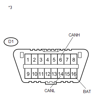
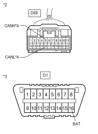
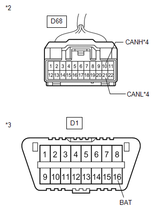
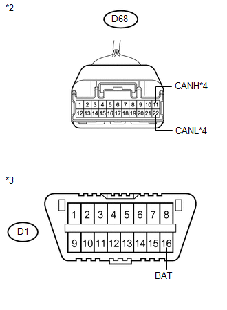
There may be a short circuit between the CAN bus main wire and +B when no resistance exists between terminals 6 (CANH) and 16 (BAT) or 14 (CANL) and 16 (BAT) of the DLC3.
|
Symptom |
Trouble Area |
|---|---|
|
No resistance exists between terminals 6 (CANH) and 16 (BAT) or 14 (CANL) and 16 (BAT) of DLC3. |
|
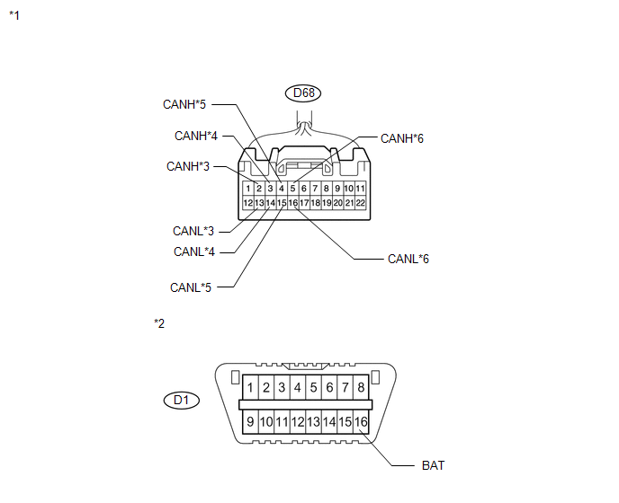
*1: for AWD
*2: w/ Smart key system
*3: w/o Smart key system
*4: for Navigation system
*5: for Audio and visual system
WIRING DIAGRAM
.png)
.png)
CAUTION / NOTICE / HINT
NOTICE:
- Turn the ignition switch off before measuring the resistances between CAN bus main wires and between CAN bus branch wires.
- Turn the ignition switch off before inspecting CAN bus wires for a ground short.
- After the ignition switch is turned off, check that the key reminder warning system and light reminder warning system are not operating.
- Before measuring the resistance, leave the vehicle as is for at least 1 minute and do not operate the ignition switch, any other switches or the doors. If any doors need to be opened in order to check connectors, open the doors and leave them open.
HINT:
- Operating the ignition switch, any other switches or a door triggers related ECU and sensor communication on the CAN. This communication will cause the resistance value to change.
- Even after DTCs are cleared, if a DTC is stored again after driving the vehicle for a while, the malfunction may be occurring due to vibration of the vehicle. In such a case, wiggling the ECUs or wire harness while performing the inspection below may help determine the cause of the malfunction.
PROCEDURE
|
1. |
CHECK FOR SHORT TO +B IN CAN BUS WIRE (CAN NO. 1 J/C) |
(a) Disconnect the cable from the negative (-) battery terminal.
|
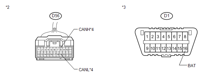
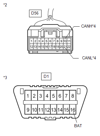
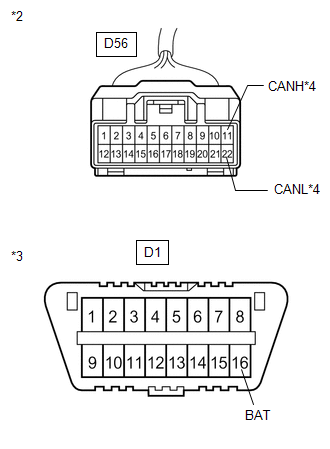
(b) Disconnect the CAN No. 1 junction connector (D56). Text in Illustration
|
|
.png)
|
(c) Measure the resistance according to the value(s) in the table below. Standard Resistance:
|
|
| NG | .gif) |
GO TO STEP 4 |
|
.gif)
|
2. |
CHECK FOR SHORT TO +B IN CAN BUS WIRE (CAN NO. 1 J/C) |
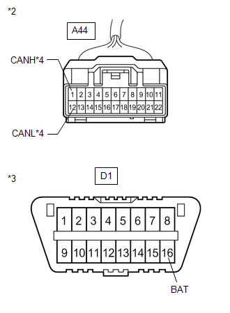
(a) Disconnect the CAN No. 1 junction connector (A44).
(b) Measure the resistance according to the value(s) in the table below.
Standard Resistance:
|
Tester Connection |
Condition |
Specified Condition |
Connected to |
|---|---|---|---|
|
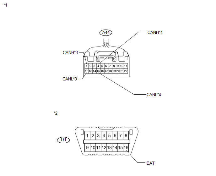
A44-1 (CANH) - D1-16 (BAT) |
Cable disconnected from negative (-) battery terminal |
6 kΩ or higher |
Skid control ECU |
|
A44-12 (CANL) - D1-16 (BAT) |
Cable disconnected from negative (-) battery terminal |
6 kΩ or higher |
|
|
A44-4 (CANH) - D1-16 (BAT) |
Cable disconnected from negative (-) battery terminal |
6 kΩ or higher |
ECM |
|
A44-15 (CANL) - D1-16 (BAT) |
Cable disconnected from negative (-) battery terminal |
6 kΩ or higher |
|
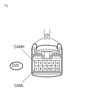
*1 |
Front view of wire harness connector (to CAN No. 1 Junction Connector) |
|
*2 |
DLC3 |
|
*3 |
to Skid Control ECU |
|
*4 |
to ECM |
|
Result |
Proceed to |
|---|---|
|
OK |
A |
|
NG (Skid control ECU branch wire) |
B |
|
NG (ECM main wire) |
C |
| B | |
GO TO STEP 8 |
| C | |
GO TO STEP 9 |
|
|
3. |
CHECK FOR SHORT TO +B IN CAN BUS WIRE (CAN NO. 1 J/C) |
(a) Measure the resistance according to the value(s) in the table below.
Standard Resistance:
|
Tester Connection |
Condition |
Specified Condition |
Connected to |
|---|---|---|---|
|
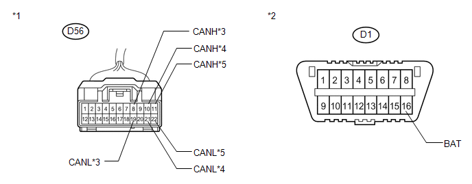
D56-8 (CANH) - D1-16 (BAT) |
Cable disconnected from negative (-) battery terminal |
6 kΩ or higher |
Air conditioning amplifier*1 |
|
D56-19 (CANL) - D1-16 (BAT) |
Cable disconnected from negative (-) battery terminal |
6 kΩ or higher |
|
|
D56-10 (CANH) - D1-16 (BAT) |
Cable disconnected from negative (-) battery terminal |
6 kΩ or higher |
Power management control ECU*2 |
|
D56-21 (CANL) - D1-16 (BAT) |
Cable disconnected from negative (-) battery terminal |
6 kΩ or higher |
|
|
D56-11 (CANH) - D1-16 (BAT) |
Cable disconnected from negative (-) battery terminal |
6 kΩ or higher |
4WD control ECU*3 |
|
D56-22 (CANL) - D1-16 (BAT) |
Cable disconnected from negative (-) battery terminal |
6 kΩ or higher |
- *1: w/o Smart key system
- *2: w/ Smart key system
- *3: for AWD
|
*1 |
Front view of wire harness connector (to CAN No. 1 Junction Connector) |
|
*2 |
DLC3 |
|
*3 |
to Air Conditioning Amplifier |
|
*4 |
to Power Management Control ECU |
|
*5 |
to 4WD Control ECU |
|
Result |
Proceed to |
|---|---|
|
OK |
A |
|
NG (Air conditioning amplifier branch wire) |
B |
|
NG (Power management control ECU branch wire) |
C |
|
NG (4WD control ECU branch wire) |
D |
| A | |
REPLACE CAN NO. 1 J/C |
| B | |
GO TO STEP 10 |
| C | |
GO TO STEP 11 |
| D | |
GO TO STEP 12 |
|
4. |
CHECK FOR SHORT TO +B IN CAN BUS WIRE (CAN NO. 2 J/C - CAN NO. 1 J/C) |
|
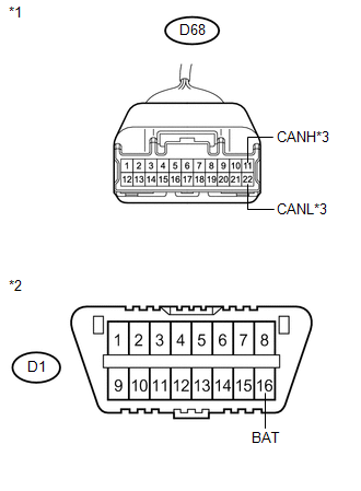
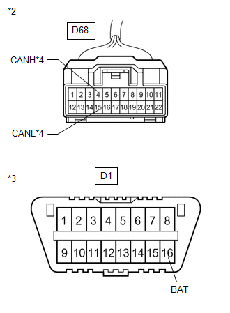
(a) Disconnect the CAN No. 2 junction connector. Text in Illustration
|
|
(b) Measure the resistance according to the value(s) in the table below.
Standard Resistance:
|
Tester Connection |
Condition |
Specified Condition |
|---|---|---|
|
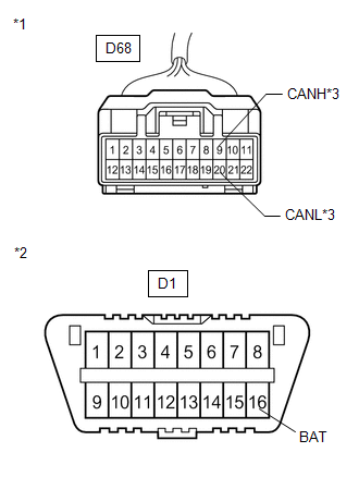
D68-9 (CANH) - D1-16 (BAT) |
Cable disconnected from negative (-) battery terminal |
6 kΩ or higher |
|
D68-20 (CANL) - D1-16 (BAT) |
Cable disconnected from negative (-) battery terminal |
6 kΩ or higher |
| NG | |
REPAIR OR REPLACE CAN BUS MAIN WIRE OR CONNECTOR (CAN NO. 2 J/C - CAN NO. 1 J/C) |
|
|
5. |
CHECK FOR SHORT TO +B IN CAN BUS WIRE (CAN NO. 2 J/C) |
(a) Measure the resistance according to the value(s) in the table below.
Standard Resistance:
|
Tester Connection |
Condition |
Specified Condition |
Connected to |
|---|---|---|---|
|
D68-2 (CANH) - D1-16 (BAT) |
Cable disconnected from negative (-) battery terminal |
6 kΩ or higher |
Center airbag sensor assembly |
|
D68-13 (CANL) - D1-16 (BAT) |
Cable disconnected from negative (-) battery terminal |
6 kΩ or higher |
|
|
D68-3 (CANH) - D1-16 (BAT) |
Cable disconnected from negative (-) battery terminal |
6 kΩ or higher |
Yaw rate sensor |
|
D68-14 (CANL) - D1-16 (BAT) |
Cable disconnected from negative (-) battery terminal |
6 kΩ or higher |
|
|
D68-4 (CANH) - D1-16 (BAT) |
Cable disconnected from negative (-) battery terminal |
6 kΩ or higher |
Main body ECU |
|
D68-15 (CANL) - D1-16 (BAT) |
Cable disconnected from negative (-) battery terminal |
6 kΩ or higher |
|
|
D68-5 (CANH) - D1-16 (BAT) |
Cable disconnected from negative (-) battery terminal |
6 kΩ or higher |
Steering angle sensor |
|
D68-16 (CANL) - D1-16 (BAT) |
Cable disconnected from negative (-) battery terminal |
6 kΩ or higher |
|
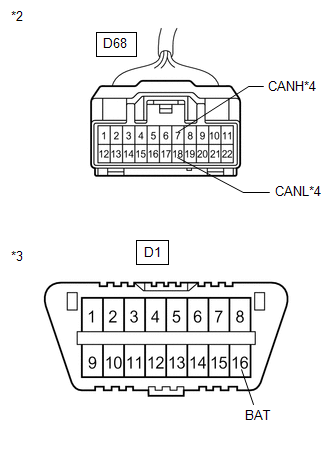
*1 |
Front view of wire harness connector (to CAN No. 2 Junction Connector) |
|
*2 |
DLC3 |
|
*3 |
to Center Airbag Sensor Assembly |
|
*4 |
to Yaw Rate Sensor |
|
*5 |
to Main Body ECU |
|
*6 |
to Steering Angle Sensor |
|
Result |
Proceed to |
|---|---|
|
OK |
A |
|
NG (Center airbag sensor assembly branch wire) |
B |
|
NG (Yaw rate sensor branch wire) |
C |
|
NG (Main body ECU branch wire) |
D |
|
NG (Steering angle sensor branch wire) |
E |
| B | |
GO TO STEP 13 |
| C | |
GO TO STEP 14 |
| D | |
GO TO STEP 15 |
| E | |
GO TO STEP 16 |
|
|
6. |
CHECK FOR SHORT TO +B IN CAN BUS WIRE (CAN NO. 2 J/C) |
(a) Measure the resistance according to the value(s) in the table below.
Standard Resistance:
|
Tester Connection |
Condition |
Specified Condition |
Connected to |
|---|---|---|---|
|
D68-6 (CANH) - D1-16 (BAT) |
Cable disconnected from negative (-) battery terminal |
6 kΩ or higher |
DLC3 |
|
D68-17 (CANL) - D1-16 (BAT) |
Cable disconnected from negative (-) battery terminal |
6 kΩ or higher |
|
|
D68-7 (CANH) - D1-16 (BAT) |
Cable disconnected from negative (-) battery terminal |
6 kΩ or higher |
Power steering ECU |
|
D68-18 (CANL) - D1-16 (BAT) |
Cable disconnected from negative (-) battery terminal |
6 kΩ or higher |
|
|
D68-8 (CANH) - D1-16 (BAT) |
Cable disconnected from negative (-) battery terminal |
6 kΩ or higher |
Combination meter |
|
D68-19 (CANL) - D1-16 (BAT) |
Cable disconnected from negative (-) battery terminal |
6 kΩ or higher |
|
|
D68-10 (CANH) - D1-16 (BAT) |
Cable disconnected from negative (-) battery terminal |
6 kΩ or higher |
Certification ECU*1 |
|
D68-21 (CANL) - D1-16 (BAT) |
Cable disconnected from negative (-) battery terminal |
6 kΩ or higher |
- *1: w/ Smart key system
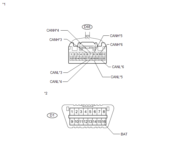
|
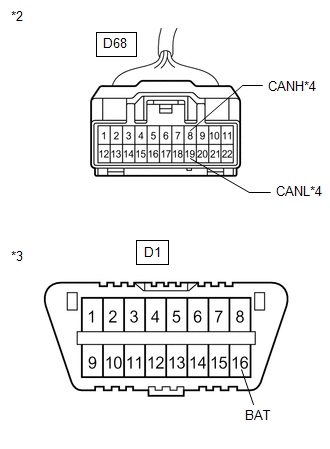
*1 |
Front view of wire harness connector (to CAN No. 2 Junction Connector) |
|
*2 |
DLC3 |
|
*3 |
to DLC3 |
|
*4 |
to Power Steering ECU |
|
*5 |
to Combination Meter |
|
*6 |
to Certification ECU |
|
Result |
Proceed to |
|---|---|
|
OK |
A |
|
NG (DLC3 branch wire) |
B |
|
NG (Power steering ECU branch wire) |
C |
|
NG (Combination meter main wire) |
D |
|
NG (Certification ECU branch wire) |
E |
| B | |
REPAIR OR REPLACE CAN BRANCH WIRE CONNECTED TO DLC3 |
| C | |
GO TO STEP 17 |
| D | |
GO TO STEP 18 |
| E | |
GO TO STEP 19 |
|
|
7. |
CHECK FOR SHORT TO +B IN CAN BUS WIRE (CAN NO. 2 J/C) |
|
(a) Measure the resistance according to the value(s) in the table below. Standard Resistance:
Result:
|
|
| A | |
REPLACE CAN NO. 2 J/C |
| B | |
GO TO STEP 20 |
| C | |
GO TO STEP 21 |
|
8. |
CHECK FOR SHORT TO +B IN CAN BUS WIRE (CAN NO. 1 J/C - SKID CONTROL ECU) |
|
(a) Disconnect the skid control ECU connector. Text in Illustration
|
|
.png)
|
(b) Measure the resistance according to the value(s) in the table below. Standard Resistance:
|
|
| OK | |
REPLACE BRAKE ACTUATOR (SKID CONTROL ECU) |
| NG | |
REPAIR OR REPLACE CAN BUS BRANCH WIRE OR CONNECTOR (CAN NO. 1 J/C - SKID CONTROL ECU) |
|
9. |
CHECK FOR SHORT TO +B IN CAN BUS WIRE (CAN NO. 1 J/C - ECM) |
|
(a) Disconnect the ECM connector. Text in Illustration
|
|
.png)
|
(b) Measure the resistance according to the value(s) in the table below. Standard Resistance:
|
|

|
Result |
Proceed to |
|---|---|
|
OK (for 1AR-FE) |
A |
|
OK (for 2GR-FE) |
B |
|
NG |
C |
| A | |
REPLACE ECM |
| B | |
REPLACE ECM |
| C | |
REPAIR OR REPLACE CAN BUS MAIN WIRE OR CONNECTOR (CAN NO. 1 J/C - ECM) |
|
10. |
CHECK FOR SHORT TO +B IN CAN BUS WIRE (CAN NO. 1 J/C - AIR CONDITIONING AMPLIFIER) |
|
(a) Disconnect the air conditioning amplifier connector. Text in Illustration
|
|
.png)
(b) Measure the resistance according to the value(s) in the table below.
Standard Resistance:
|
Tester Connection |
Condition |
Specified Condition |
|---|---|---|
|
D56-8 (CANH) - D1-16 (BAT) |
Cable disconnected from negative (-) battery terminal |
6 kΩ or higher |
|
D56-19 (CANL) - D1-16 (BAT) |
Cable disconnected from negative (-) battery terminal |
6 kΩ or higher |
|
*2 |
Front view of wire harness connector (to CAN No. 1 Junction Connector) |
|
*3 |
DLC3 |
|
*4 |
to Air Conditioning Amplifier |
| OK | |
REPLACE AIR CONDITIONING AMPLIFIER |
| NG | |
REPAIR OR REPLACE CAN BUS BRANCH WIRE OR CONNECTOR (CAN NO. 1 J/C - AIR CONDITIONING AMPLIFIER) |
|
11. |
CHECK FOR SHORT TO +B IN CAN BUS WIRE (CAN NO. 1 J/C - POWER MANAGEMENT CONTROL ECU) |
|
(a) Disconnect the power management control ECU connector. Text in Illustration
|
|
.png)
|
(b) Measure the resistance according to the value(s) in the table below. Standard Resistance:
|
|
| OK | |
REPLACE POWER MANAGEMENT CONTROL ECU |
| NG | |
REPAIR OR REPLACE CAN BUS BRANCH WIRE OR CONNECTOR (CAN NO. 1 J/C - POWER MANAGEMENT CONTROL ECU) |
|
12. |
CHECK FOR SHORT TO +B IN CAN BUS WIRE (CAN NO. 1 J/C - 4WD CONTROL ECU) |
|
(a) Disconnect the 4WD control ECU connector. Text in Illustration
|
|
.png)
|
(b) Measure the resistance according to the value(s) in the table below. Standard Resistance:
|
|
| OK | |
REPLACE 4WD CONTROL ECU |
| NG | |
REPAIR OR REPLACE CAN BUS BRANCH WIRE OR CONNECTOR (CAN NO. 1 J/C - 4WD CONTROL ECU) |
|
13. |
CHECK FOR SHORT TO +B IN CAN BUS WIRE (CAN NO. 2 J/C - CENTER AIRBAG SENSOR ASSEMBLY) |
|
(a) Disconnect the center airbag sensor assembly connector. Text in Illustration
|
|
.png)
|
(b) Measure the resistance according to the value(s) in the table below. Standard Resistance:
|
|

| OK | |
REPLACE CENTER AIRBAG SENSOR ASSEMBLY |
| NG | |
REPAIR OR REPLACE CAN BUS BRANCH WIRE OR CONNECTOR (CAN NO. 2 J/C - CENTER AIRBAG SENSOR ASSEMBLY) |
|
14. |
CHECK FOR SHORT TO +B IN CAN BUS WIRE (CAN NO. 2 J/C - YAW RATE SENSOR) |
|
(a) Disconnect the yaw rate sensor connector. Text in Illustration
|
|
.png)
|
(b) Measure the resistance according to the value(s) in the table below. Standard Resistance:
|
|

| OK | |
REPLACE YAW RATE SENSOR |
| NG | |
REPAIR OR REPLACE CAN BUS BRANCH WIRE OR CONNECTOR (CAN NO. 2 J/C - YAW RATE SENSOR) |
|
15. |
CHECK FOR SHORT TO +B IN CAN BUS WIRE (CAN NO. 2 J/C - MAIN BODY ECU) |
|
(a) Disconnect the main body ECU connector. Text in Illustration
|
|
.png)
|
(b) Measure the resistance according to the value(s) in the table below. Standard Resistance:
|
|
| OK | |
REPLACE MAIN BODY ECU (DRIVER SIDE JUNCTION BLOCK) |
| NG | |
REPAIR OR REPLACE CAN BUS BRANCH WIRE OR CONNECTOR (CAN NO. 2 J/C - MAIN BODY ECU) |
|
16. |
CHECK FOR SHORT TO +B IN CAN BUS WIRE (CAN NO. 2 J/C - STEERING ANGLE SENSOR) |
|
(a) Disconnect the steering angle sensor connector. Text in Illustration
|
|
.png)
|
(b) Measure the resistance according to the value(s) in the table below. Standard Resistance:
|
|
| OK | |
REPLACE STEERING ANGLE SENSOR |
| NG | |
REPAIR OR REPLACE CAN BUS BRANCH WIRE OR CONNECTOR (CAN NO. 2 J/C - STEERING ANGLE SENSOR) |
|
17. |
CHECK FOR SHORT TO +B IN CAN BUS WIRE (CAN NO. 2 J/C - POWER STEERING ECU) |
|
(a) Disconnect the power steering ECU connector. Text in Illustration
|
|
|
(b) Measure the resistance according to the value(s) in the table below. Standard Resistance:
|
|
| OK | |
REPLACE POWER STEERING ECU |
| NG | |
REPAIR OR REPLACE CAN BUS BRANCH WIRE OR CONNECTOR (CAN NO. 2 J/C - POWER STEERING ECU) |
|
18. |
CHECK FOR SHORT TO +B IN CAN BUS WIRE (CAN NO. 2 J/C - COMBINATION METER) |
|
(a) Disconnect the combination meter connector. Text in Illustration
|
|
.png)
|
(b) Measure the resistance according to the value(s) in the table below. Standard Resistance:
|
|
| OK | |
REPLACE COMBINATION METER |
| NG | |
REPAIR OR REPLACE CAN BUS MAIN WIRE OR CONNECTOR (CAN NO. 2 J/C - COMBINATION METER) |
|
19. |
CHECK FOR SHORT TO +B IN CAN BUS WIRE (CAN NO. 2 J/C - CERTIFICATION ECU) |
|
(a) Disconnect the certification ECU connector. Text in Illustration
|
|
.png)
|
(b) Measure the resistance according to the value(s) in the table below. Standard Resistance:
|
|
| OK | |
REPLACE SMART KEY ECU ASSEMBLY (CERTIFICATION ECU) |
| NG | |
REPAIR OR REPLACE CAN BUS BRANCH WIRE OR CONNECTOR (CAN NO. 2 J/C - CERTIFICATION ECU) |
|
20. |
CHECK FOR SHORT TO +B IN CAN BUS WIRE (CAN NO. 2 J/C - NAVIGATION RECEIVER ASSEMBLY) |
|
(a) Disconnect the navigation receiver assembly connector. Text in Illustration
|
|
.png)
|
(b) Measure the resistance according to the value(s) in the table below. Standard Resistance:
|
|
| OK | |
REPLACE NAVIGATION RECEIVER ASSEMBLY |
| NG | |
REPAIR OR REPLACE CAN BUS BRANCH WIRE OR CONNECTOR (CAN NO. 2 J/C - NAVIGATION RECEIVER ASSEMBLY) |
|
21. |
CHECK FOR SHORT TO +B IN CAN BUS WIRE (CAN NO. 2 J/C - RADIO AND DISPLAY RECEIVER ASSEMBLY) |
|
(a) Disconnect the radio and display receiver assembly connector. Text in Illustration
|
|
.png)
|
(b) Measure the resistance according to the value(s) in the table below. Standard Resistance:
|
|
| OK | |
REPLACE RADIO AND DISPLAY RECEIVER ASSEMBLY |
| NG | |
REPAIR OR REPLACE CAN BUS BRANCH WIRE OR CONNECTOR (CAN NO. 2 J/C - RADIO AND DISPLAY RECEIVER ASSEMBLY) |
 Check CAN Bus Lines for Short Circuit
DESCRIPTION
There may be a short circuit in the CAN bus main wire and/or CAN branch wire
when the resistance between terminals 6 (CANH) and 14 (CANL) of the DLC3 is below
54 Ω.
Sympt ...
 Check CAN Bus Line for Short to GND
DESCRIPTION
There may be a short circuit between the CAN bus main wire and GND when there
is no resistance between terminals 6 (CANH) and 4 (CG) or 14 (CANL) and 4 (CG) of
the DLC3.
S ...
Other materials about Toyota Venza:
Drive Shaft System
Precaution
PRECAUTION
1. NOTICE OF REMOVING AND INSTALLING FRONT DRIVE SHAFT ASSEMBLY RH
(a) When removing and installing the front drive shaft assembly RH in a AWD vehicle,
be sure to first drain all the transaxle oil and transfer oil. If removal and i ...
Terminals Of Ecu
TERMINALS OF ECU
1. COMBINATION METER ASSEMBLY
(a) Measure the voltage and resistance according to the value(s) in the table
below.
Terminal No. (Symbol)
Wiring Color
Terminal Description
Condition
...
Check CAN Bus Lines for Short Circuit
DESCRIPTION
There may be a short circuit in the CAN bus main wire and/or CAN branch wire
when the resistance between terminals 6 (CANH) and 14 (CANL) of the DLC3 is below
54 Ω.
Symptom
Trouble Area
Resistance betwe ...

0.1641