Toyota Venza: Bleeding
BLEEDING
CAUTION / NOTICE / HINT
NOTICE:
- Do not allow brake fluid to adhere to any painted surface such as the vehicle body. If brake fluid leaks onto any painted surface, immediately wash it off.
- Before bleeding the brake system, confirm that the reservoir located above the master cylinder assembly is filled with brake fluid.
- If bleeding is performed with the engine running or the engine switch on (IG), DTC C1441 will be stored. Make sure to clear the DTCs when work is complete.
HINT:
If any component of the brake system is removed and reinstalled, or if air in the brake lines is suspected, bleed the brake system.
PROCEDURE
1. FILL RESERVOIR WITH BRAKE FLUID
.gif)
2. BLEED BRAKE MASTER CYLINDER
NOTICE:
- To prevent brake fluid from damaging painted surfaces, cover any surrounding parts with a piece of cloth.
- Be sure to clean your hands before bleeding from master cylinder to avoid any potential contamination of the brake system. Contamination, for example by dirt particles or mineral oil, could lead to functional brake problem.
HINT:
If the master cylinder is reinstalled or runs out of brake fluid, bleed the master cylinder.
|
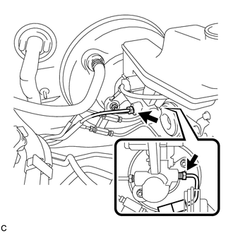
(a) Using a union nut wrench, disconnect the 2 brake tubes from the brake master cylinder assembly. |
|
|
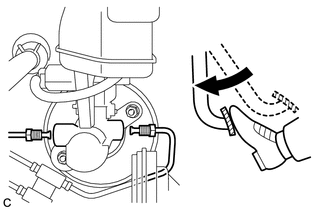
(b) Slowly depress the brake pedal and hold it down. |
|
|
(c) Cover the 2 tube holes with your fingers and release the brake pedal. |
|
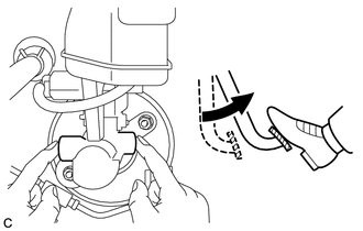
(d) Uncover the holes, slowly depress the brake pedal and hold it down. While holding down the brake pedal, cover the tube holes again. Repeat this step 3 or 4 times.
|
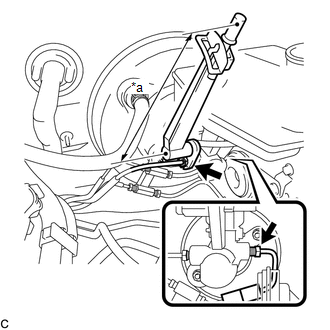
(e) Using a union nut wrench, connect the 2 brake tubes to the brake master cylinder assembly. Text in Illustration
Torque: Specified Tightening Torque : 20 N·m {199 kgf·cm, 14 ft·lbf} NOTICE:
HINT:
|
|
3. BLEED BRAKE LINE
4. INSPECT FOR BRAKE FLUID LEAK
5. INSPECT FLUID LEVEL IN RESERVOIR
6. CHECK AND CLEAR DTC
(See page )
 Replacement
REPLACEMENT
CAUTION / NOTICE / HINT
NOTICE:
Move the shift lever to P and apply the parking brake before bleeding
the brakes.
Add brake fluid to keep the level between the MIN and M ...
 Brake Line
Precaution
PRECAUTION
1. TROUBLESHOOTING PRECAUTION
NOTICE:
Since the brake lines are critical safety related parts, be sure to
disassemble and inspect the components if a brake flui ...
Other materials about Toyota Venza:
How To Proceed With Troubleshooting
CAUTION / NOTICE / HINT
HINT:
Use the following procedure to troubleshoot.
*: Use the Techstream.
PROCEDURE
1.
VEHICLE BROUGHT TO WORKSHOP
NEXT
...
Air Mix Damper Control Servo Motor Circuit (Driver Side) (B1446/46)
DESCRIPTION
The air mix control servo motor sends pulse signals to indicate the damper position
to the A/C amplifier. The A/C amplifier activates the motor (normal or reverse)
based on these signals to move the air mix damper (driver side) to any position ...
Disassembly
DISASSEMBLY
PROCEDURE
1. REMOVE UPPER BACK WINDOW PANEL TRIM
(a) Disengage the 4 clips and 4 claws, and remove the upper back window
panel trim.
2. REMOVE BACK DOOR PANEL TRIM ASSEMBLY
...

0.1764