Toyota Venza: Outer Mirror Control Ecu
Components
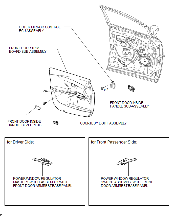
COMPONENTS
ILLUSTRATION
Removal
REMOVAL
PROCEDURE
1. REMOVE FRONT DOOR INSIDE HANDLE BEZEL PLUG
.gif)
2. REMOVE POWER WINDOW REGULATOR MASTER SWITCH ASSEMBLY WITH FRONT DOOR ARMREST BASE PANEL (for Driver Side)
3. REMOVE POWER WINDOW REGULATOR SWITCH ASSEMBLY WITH FRONT DOOR ARMREST BASE PANEL (for Front Passenger Side)
4. REMOVE COURTESY LIGHT ASSEMBLY
5. REMOVE FRONT DOOR TRIM BOARD SUB-ASSEMBLY
6. REMOVE FRONT DOOR INSIDE HANDLE SUB-ASSEMBLY
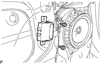
7. REMOVE OUTER MIRROR CONTROL ECU ASSEMBLY
|
(a) Disconnect the 2 connectors. |
|
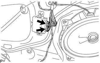
|
(b) Remove the 2 screws and outer mirror control ECU assembly. |
|
Installation
INSTALLATION
PROCEDURE
1. INSTALL OUTER MIRROR CONTROL ECU ASSEMBLY
(a) Install the outer mirror control ECU assembly with the 2 screws.
(b) Connect the 2 connectors.
2. INSTALL FRONT DOOR INSIDE HANDLE SUB-ASSEMBLY
.gif)
3. INSTALL FRONT DOOR TRIM BOARD SUB-ASSEMBLY
4. INSTALL COURTESY LIGHT ASSEMBLY
5. INSTALL POWER WINDOW REGULATOR MASTER SWITCH ASSEMBLY WITH FRONT DOOR ARMREST BASE PANEL (for Driver Side)
6. INSTALL POWER WINDOW REGULATOR SWITCH ASSEMBLY WITH FRONT DOOR ARMREST BASE PANEL (for Front Passenger Side)
7. INSTALL FRONT DOOR INSIDE HANDLE BEZEL PLUG
 Mirror (ext)
...

Other materials about Toyota Venza:
Pcv Valve
Components
COMPONENTS
ILLUSTRATION
Removal
REMOVAL
PROCEDURE
1. REMOVE INTAKE MANIFOLD
(a) Remove the intake manifold (See page ).
2. REMOVE VENTILATION VALVE SUB-ASSEMBLY
(a) Disconnect the No. 2 ventilation hose from the ventilatio ...
Satellite Radio Antenna
Components
COMPONENTS
ILLUSTRATION
ILLUSTRATION
Removal
REMOVAL
PROCEDURE
1. REMOVE ROOF HEADLINING ASSEMBLY
(See page )
2. REMOVE ROOF ANTENNA POLE SUB-ASSEMBLY
3. REMOVE SATELLITE RADIO ANTENNA ASSEMBLY
(a) Disconnect the co ...
Installation
INSTALLATION
PROCEDURE
1. INSTALL YAW RATE AND ACCELERATION SENSOR
(a) Install the yaw rate and acceleration sensor to the bracket with
the 2 nuts.
Torque:
5.0 N·m {51 kgf·cm, 44 in·lbf}
...

0.1809