Toyota Venza: Voice Recognition Microphone Disconnected (B1579)
DESCRIPTION
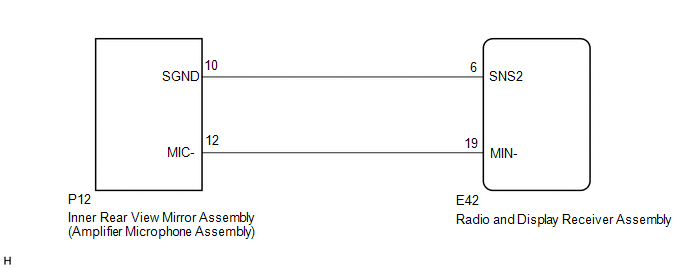
The radio and display receiver assembly and inner rear view mirror assembly (amplifier microphone assembly) are connected to each other using the microphone connection detection signal lines.
This DTC is stored when a microphone connection detection signal line is disconnected.
|
DTC No. |
DTC Detection Condition |
Trouble Area |
|---|---|---|
|
B1579 |
Microphone signal is lost. |
|
WIRING DIAGRAM
PROCEDURE
|
1. |
INSPECT RADIO AND DISPLAY RECEIVER ASSEMBLY |
|
(a) Measure the resistance according to the value(s) in the table below. Standard Resistance:
|
|
| NG | .gif) |
REPLACE RADIO AND DISPLAY RECEIVER ASSEMBLY |
|
.gif)
|
2. |
CHECK HARNESS AND CONNECTOR (RADIO AND DISPLAY RECEIVER ASSEMBLY - INNER REAR VIEW MIRROR ASSEMBLY (AMPLIFIER MICROPHONE ASSEMBLY)) |
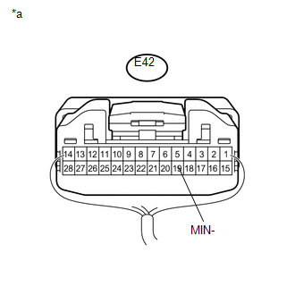
(a) Disconnect the E42 radio and display receiver assembly connector.
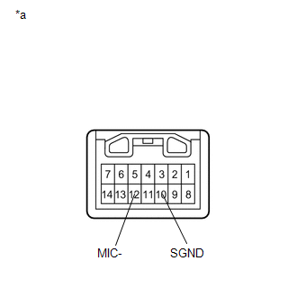
(b) Disconnect the P12 inner rear view mirror assembly (amplifier microphone assembly) connector.
(c) Measure the resistance according to the value(s) in the table below.
Standard Resistance:
|
Tester Connection |
Condition |
Specified Condition |
|---|---|---|
|
E42-6 (SNS2) - P12-10 (SGND) |
Always |
Below 1 Ω |
|
E42-19 (MIN-) - P12-12 (MIC-) |
Always |
Below 1 Ω |
|
E42-6 (SNS2) - Body ground |
Always |
10 kΩ or higher |
|
E42-19 (MIN-) - Body ground |
Always |
10 kΩ or higher |
| NG | |
REPAIR OR REPLACE HARNESS OR CONNECTOR |
|
|
3. |
INSPECT INNER REAR VIEW MIRROR ASSEMBLY (AMPLIFIER MICROPHONE ASSEMBLY) |
(a) Remove the inner rear view mirror assembly (amplifier microphone assembly)
(See page .gif) ).
).
|
(b) Measure the resistance according to the value(s) in the table below. Standard Resistance:
|
|
| OK | |
REPLACE RADIO AND DISPLAY RECEIVER ASSEMBLY |
| NG | |
REPLACE INNER REAR VIEW MIRROR ASSEMBLY (AMPLIFIER MICROPHONE ASSEMBLY) |
 AV Signal Stoppage (Low Battery Voltage) (B158F)
DESCRIPTION
This DTC is stored when a video or audio signal is interrupted due to battery
voltage input to the radio and display receiver assembly dropping temporarily.
DTC No.
...
 USB Device Malfunction (B1585)
DESCRIPTION
This DTC is stored when a malfunction occurs in a connected device.
DTC No.
DTC Detection Condition
Trouble Area
B1585
When a ...
Other materials about Toyota Venza:
Lost Communication with Front Airbag Sensor RH (B1612/83,B1613/83)
DESCRIPTION
The front airbag sensor RH circuit consists of the center airbag sensor assembly
and front airbag sensor RH.
The front airbag sensor RH detects impacts to the vehicle and sends signals to
the center airbag sensor assembly to determine if the ...
How To Proceed With Troubleshooting
CAUTION / NOTICE / HINT
HINT:
Use the following procedure to troubleshoot the air conditioning system.
*: Use the Techstream.
PROCEDURE
1.
VEHICLE BROUGHT TO WORKSHOP
NEXT
...
Certification ECU Communication Stop Mode
DESCRIPTION
Detection Item
Symptom
Trouble Area
Certification ECU Communication Stop Mode
"Smart Access/Smart Key/Wireless Tuner" is not displayed on
"CAN Bus Check&q ...

0.1236