Toyota Venza: Air Outlet Damper Control Servo Motor Circuit (B1443/43)
DESCRIPTION
The air outlet control servo motor sends pulse signals to indicate the damper position to the A/C amplifier. The A/C amplifier activates the motor (normal or reverse) based on these signals to move the mode damper to any position, which controls the air outlet switching.
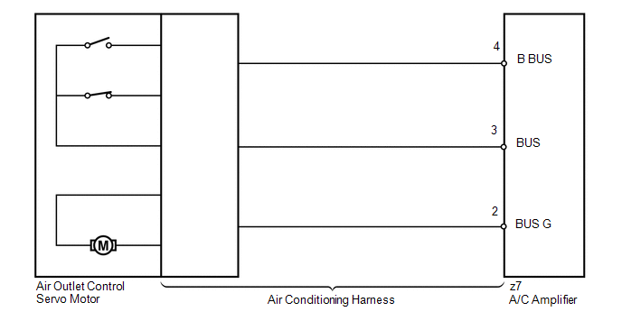
The A/C amplifier communicates with the servo through a communication/driver IC and wiring assembly called the air conditioning harness.
HINT:
Confirm that no mechanical problem is present because this DTC can be output when either a damper link or the damper is mechanically locked.
|
DTC No. |
DTC Detection Condition |
Trouble Area |
|---|---|---|
|
B1443/43 |
Air outlet damper position sensor value does not change even if A/C amplifier operates air outlet control servo motor |
|
WIRING DIAGRAM
PROCEDURE
|
1. |
READ VALUE USING TECHSTREAM |
(a) Connect the Techstream to the DLC3.
(b) Turn the ignition switch to ON.
(c) Turn the Techstream on.
(d) Operate the MODE switch.
(e) Enter the following menus: Body / Air Conditioner / Data List.
(f) Check the value(s) by referring to the table below.
Air Conditioner|
Tester Display |
Measurement Item/Range |
Normal Condition |
Diagnostic Note |
|---|---|---|---|
|
Air Outlet Servo Pulse (D) |
Air outlet servo motor target pulse / Min.: 0, Max.: 255 |
FACE: 8 (pulse) B/L: 30 to 38 (pulse) FOOT: 50 to 74 (pulse) FOOT/DEF: 80 (pulse) DEF: 97 (pulse) |
- |
OK:
The display is as specified in the Normal Condition column.
|
Result |
Proceed to |
|---|---|
|
NG |
A |
|
OK (When troubleshooting according to Problem Symptoms Table) |
B |
|
OK (When troubleshooting according to the DTC) |
C |
| B | .gif) |
PROCEED TO NEXT SUSPECTED AREA SHOWN IN PROBLEM SYMPTOMS TABLE |
| C | |
REPLACE A/C AMPLIFIER |
|
.gif)
|
2. |
PERFORM ACTIVE TEST USING TECHSTREAM |
(a) Connect the Techstream to the DLC3.
(b) Turn the ignition switch to ON.
(c) Turn the Techstream on.
(d) Enter the following menus: Body / Air Conditioner / Active Test.
(e) Check the operation by referring to the table below.
Air Conditioner|
Tester Display |
Test Part |
Control Rage |
Diagnostic Note |
|---|---|---|---|
|
Air Outlet Servo Pulse (D) |
Air outlet servo motor pulse |
Min.: 0, Max.: 255 |
- |
OK:
Air flow position changes in accordance with each control range.
| OK | |
REPLACE A/C AMPLIFIER |
|
|
3. |
INSPECT AIR OUTLET CONTROL SERVO MOTOR |
(a) Replace the No. 1 air mix control servo motor (air outlet control servo motor)
(See page .gif) ).
).
HINT:
Since the servo motor cannot be inspected while it is removed from the vehicle, replace the servo motor with a new or a known good one and check that the condition returns to normal.
(b) Check for the DTC.
|
Result |
Proceed to |
|---|---|
|
DTC B1443/43 is output |
A |
|
DTC B1443/43 is not output |
B |
| B | |
REPLACE AIR OUTLET CONTROL SERVO MOTOR |
|
|
4. |
INSPECT AIR CONDITIONING HARNESS |
(a) Replace the air conditioning harness (See page
).
HINT:
Since the air conditioning harness cannot be inspected while it is removed from the vehicle, replace the air conditioning harness with a new or a known good one and check that the condition returns to normal.
(b) Check for the DTC.
|
Result |
Proceed to |
|---|---|
|
DTC B1443/43 is output |
A |
|
DTC B1443/43 is not output |
B |
| A | |
REPLACE A/C AMPLIFIER |
| B | |
REPLACE AIR CONDITIONING HARNESS |
 Air Inlet Damper Control Servo Motor Circuit (B1442/42)
DESCRIPTION
The air inlet control servo motor sends pulse signals to indicate the damper
position to the A/C amplifier. The A/C amplifier activates the motor (normal or
reverse) based on these si ...
 Air Mix Damper Control Servo Motor Circuit (Passenger Side) (B1441/41)
DESCRIPTION
The air mix control servo motor sends pulse signals to indicate the damper position
to the A/C amplifier. The A/C amplifier activates the motor (normal or reverse)
based on these sign ...
Other materials about Toyota Venza:
Diagnosis System
DIAGNOSIS SYSTEM
1. ECUS OR SENSORS WHICH COMMUNICATE THROUGH CAN COMMUNICATION SYSTEM
(a) CAN No. 1 Bus
(1) ECM
(2) Main body ECU (Driver side junction block)
(3) Combination meter
(4) Power steering ECU
(5) Air conditioning amplifier*3
(6) Center air ...
How To Proceed With Troubleshooting
CAUTION / NOTICE / HINT
HINT:
Use the following procedure to troubleshoot.
*: Use the Techstream.
PROCEDURE
1.
VEHICLE BROUGHT TO WORKSHOP
NEXT
...
License Plate Light Assembly
Components
COMPONENTS
ILLUSTRATION
ILLUSTRATION
Installation
INSTALLATION
PROCEDURE
1. INSTALL LICENSE PLATE LIGHT ASSEMBLY
(a) Engage the 2 claws to install the license plate light assembly.
...

0.1305