Toyota Venza: Air Conditioning Panel
Components
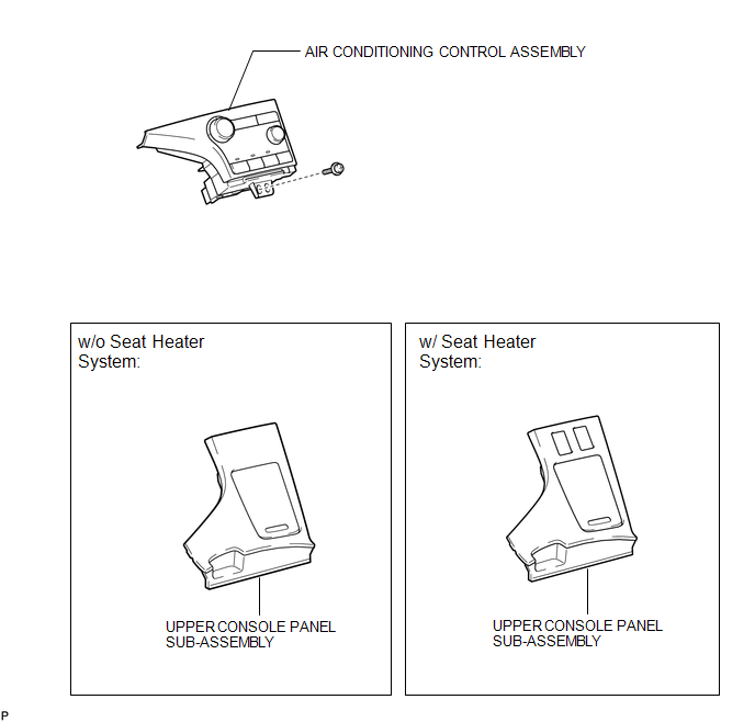
COMPONENTS
ILLUSTRATION
Installation
INSTALLATION
PROCEDURE
1. INSTALL AIR CONDITIONING CONTROL ASSEMBLY
(a) Connect the connector.
|
(b) Engage the 2 clips and 4 guides. |
|
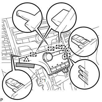
(c) Remove the protective tape.
Text in Illustration|
*1 |
Protective Tape |
|
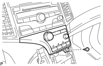
(d) Install the air conditioning control assembly with the screw. |
|
2. INSTALL UPPER CONSOLE PANEL SUB-ASSEMBLY (w/o Seat Heater System)
.gif)
3. INSTALL UPPER CONSOLE PANEL SUB-ASSEMBLY (w/ Seat Heater System)
4. CONNECT CABLE TO NEGATIVE BATTERY TERMINAL
NOTICE:
When disconnecting the cable, some systems need to be initialized after the cable
is reconnected (See page ).
Removal
REMOVAL
PROCEDURE
1. DISCONNECT CABLE FROM NEGATIVE BATTERY TERMINAL
NOTICE:
When disconnecting the cable, some systems need to be initialized after the cable
is reconnected (See page .gif) ).
).
2. REMOVE UPPER CONSOLE PANEL SUB-ASSEMBLY (w/o Seat Heater System)
3. REMOVE UPPER CONSOLE PANEL SUB-ASSEMBLY (w/ Seat Heater System)
4. REMOVE AIR CONDITIONING CONTROL ASSEMBLY
|
(a) Remove the screw. |
|
.png)
|
(b) Apply protective tape to the area shown in the illustration. Text in Illustration
|
|
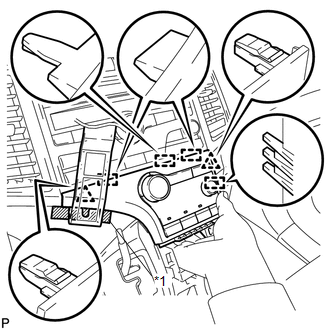
(c) Using a moulding remover, disengage the 2 clips and 4 guides as shown in the illustration.
(d) Disconnect the connector and remove the air conditioning control assembly.
 Air Conditioning Amplifier
Components
COMPONENTS
ILLUSTRATION
Installation
INSTALLATION
PROCEDURE
1. INSTALL AIR CONDITIONING AMPLIFIER ASSEMBLY
(a) Install the air conditioning amplifier assembly with t ...
 Air Conditioning Pressure Sensor
Components
COMPONENTS
ILLUSTRATION
Installation
INSTALLATION
PROCEDURE
1. INSTALL AIR CONDITIONING PRESSURE SENSOR
(a) Sufficiently apply compressor oil to a new air conditioni ...
Other materials about Toyota Venza:
How To Proceed With Troubleshooting
CAUTION / NOTICE / HINT
HINT:
*: Use the Techstream.
PROCEDURE
1.
VEHICLE BROUGHT TO WORKSHOP
NEXT
2.
CUSTOMER PROBLEM ANALYSIS
...
Brake Switch "A" / "B" Correlation (P0504)
DESCRIPTION
The stop light switch is a duplex system that transmits 2 signals: STP and ST1-.
These 2 signals are used by the ECM to monitor whether or not the brake system is
working properly. If signals which indicate the brake pedal is being depressed a ...
Reassembly
REASSEMBLY
PROCEDURE
1. INSTALL NO. 2 STEERING RACK BOOT
(a) Apply lithium soap base glycol grease to the inside of the small
opening of a new No. 2 steering rack boot.
(b) Install the No. 2 ste ...

0.133