Toyota Venza: Terminals Of Ecu
TERMINALS OF ECU
1. CHECK TRANSPONDER KEY AMPLIFIER
(a) Disconnect the D21 transponder key amplifier connector.

(b) Measure the resistance according to the value(s) in the table below.
HINT:
Measure the values on the wire harness side with connector disconnected.
|
Tester Connection |
Wiring Color |
Terminal Description |
Condition |
Specified Condition |
|---|---|---|---|---|
|
D21-7 (AGND) - Body ground |
W - Body ground |
Ground |
Always |
Below 1 Ω |
If the result is not as specified, there may be a malfunction on the wire harness side.
(c) Reconnect the D21 transponder key amplifier connector.
(d) Measure the voltage according to the value(s) in the table below.
|
Tester Connection |
Wiring Color |
Terminal Description |
Condition |
Specified Condition |
|---|---|---|---|---|
|
D21-1 (VC5) - D21-7 (AGND) |
R - W |
Power source |
No key in ignition key cylinder |
Below 1 V |
|
D21-1 (VC5) - D21-7 (AGND) |
R - W |
Power source |
Key in ignition key cylinder |
4.6 to 5.4 V |
|
D21-4 (CODE) - D21-7 (AGND) |
LG - W |
Demodulated signal of key code data |
No key in ignition key cylinder |
Below 1 V |
|
D21-4 (CODE) - D21-7 (AGND) |
LG - W |
Demodulated signal of key code data |
Key in ignition key cylinder |
Pulse generation (See waveform 1) |
|
D21-5 (TXCT) - D21-7 (AGND) |
BR - W |
Key code output signal |
No key in ignition key cylinder |
Below 1 V |
|
D21-5 (TXCT) - D21-7 (AGND) |
BR - W |
Key code output signal |
Key in ignition key cylinder |
Pulse generation (See waveform 2) |
If the result is not as specified, the transponder key amplifier may have a malfunction.
(e) Inspect using an oscilloscope.
(1) Waveform 1 (Reference)
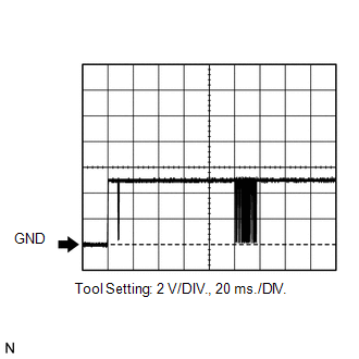
|
Tester Connection |
D21-4 (CODE) - D21-7 (AGND) |
|
Tool Setting |
2 V/DIV., 20 ms./DIV. |
|
Condition |
Key is in ignition key cylinder |
(2) Waveform 2 (Reference)
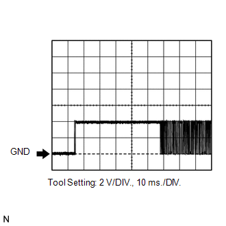
|
Tester Connection |
D21-5 (TXCT) - D21-7 (AGND) |
|
Tool Setting |
2 V/DIV., 10 ms./DIV. |
|
Condition |
Key is in ignition key cylinder |
2. CHECK TRANSPONDER KEY ECU ASSEMBLY
(a) Disconnect the D22 transponder key ECU assembly connector.

(b) Measure the resistance and voltage according to the value(s) in the table below.
HINT:
Measure the values on the wire harness side with connector disconnected.
|
Tester Connection |
Wiring Color |
Terminal Description |
Condition |
Specified Condition |
|---|---|---|---|---|
|
D22-16 (GND) - Body ground |
B - Body ground |
Ground |
Always |
Below 1 Ω |
|
D22-1 (+B) - D22-16 (GND) |
G - B |
Battery |
Always |
11 to 14 V |
|
D22-2 (IG) - D22-16 (GND) |
R - B |
Ignition switch signal |
Ignition switch off |
Below 1 V |
|
D22-2 (IG) - D22-16 (GND) |
R - B |
Ignition switch signal |
Ignition switch ON |
11 to 14 V |
|
D22-3 (KSW) - D22-16 (GND) |
V - B |
Unlock warning switch signal |
No key in ignition key cylinder |
10 kΩ or higher |
|
D22-3 (KSW) - D22-16 (GND) |
V - B |
Unlock warning switch signal |
Key in ignition key cylinder |
Below 1 Ω |
If the result is not as specified, there may be a malfunction on the wire harness side.
(c) Reconnect the D22 transponder key ECU assembly connector.
(d) Measure the resistance and voltage according to the value(s) in the table below.
|
Tester Connection |
Wiring Color |
Terminal Description |
Condition |
Specified Condition |
|---|---|---|---|---|
|
D22-5 (AGND) - Body ground |
W - Body ground |
Ground |
Always |
Below 1 Ω |
|
D22-3 (KSW) - D22-16 (GND) |
V - B |
Unlock warning switch signal |
No key in ignition key cylinder |
11 to 14 V |
|
D22-3 (KSW) - D22-16 (GND) |
V - B |
Unlock warning switch signal |
Key in ignition key cylinder |
Below 1 V |
|
D22-14 (VC5) - D22-5 (AGND) |
R - W |
Power source |
No key in ignition key cylinder |
Below 1 V |
|
D22-14 (VC5) - D22-5 (AGND) |
R - W |
Power source |
Key in ignition key cylinder |
4.6 to 5.4 V |
|
D22-4 (TXCT) - D22-5 (AGND) |
BR - W |
Transponder key amplifier communication signal |
No key in ignition key cylinder |
Below 1 V |
|
D22-4 (TXCT) - D22-5 (AGND) |
BR - W |
Transponder key amplifier communication signal |
Key in ignition key cylinder |
Pulse generation (See waveform 1) |
|
D22-15 (CODE) - D22-5 (AGND) |
LG - W |
Transponder key amplifier communication signal |
No key in ignition key cylinder |
Below 1 V |
|
D22-15 (CODE) - D22-5 (AGND) |
LG - W |
Transponder key amplifier communication signal |
Key in ignition key cylinder |
Pulse generation (See waveform 2) |
|
D22-13 (EFIO) - D22-16 (GND) |
G - B |
ECM output signal |
Ignition switch off |
Below 1 V |
|
D22-13 (EFIO) - D22-16 (GND) |
G - B |
ECM output signal |
Ignition switch ON |
Pulse generation (See waveform 3) |
|
D22-12 (EFII) - D22-16 (GND) |
BR - B |
ECM input signal |
Ignition switch off |
11 to 14 V |
|
D22-12 (EFII) - D22-16 (GND) |
BR - B |
ECM input signal |
Within 3 seconds after starter operates and initial combustion occurs, or within 3seconds after ignition switch first turned on (IG) after battery disconnected and connected. |
Pulse generation (See waveform 4) |
|
D22-9 (D) - D22-16 (GND) |
L - B |
Diagnostic tester communication |
Without communication |
Below 1 V |
|
D22-9 (D) - D22-16 (GND) |
L - B |
Diagnostic tester communication |
During communication |
Pulse generation |
|
D22-7 (CTY) - D22-16 (GND) |
G - B |
Door courtesy signal |
Switch pushed |
11 to 14 V |
|
D22-7 (CTY) - D22-16 (GND) |
G - B |
Door courtesy signal |
Switch free |
Below 1 V |
|
D22-8 (IND) - D22-16 (GND) |
Y - B |
Security indicator signal |
Ignition switch off, security indicator light blinks |
Alternating between 11 to 14 V and below 1 V |
|
D22-8 (IND) - D22-16 (GND) |
Y - B |
Security indicator signal |
Ignition switch ON, security indicator light off |
Below 1 V |
If the result is not as specified, the transponder key ECU assembly may have a malfunction.
(e) Inspect using an oscilloscope.
(1) Waveform 1 (Reference)
|
Tester Connection |
D22-4 (TXCT) - D22-5 (AGND) |
|
Tool Setting |
2 V/DIV., 10 ms./DIV. |
|
Condition |
Key is in ignition key cylinder |
(2) Waveform 2 (Reference)
|
Tester Connection |
D22-15 (CODE) - D22-5 (AGND) |
|
Tool Setting |
2 V/DIV., 20 ms./DIV. |
|
Condition |
Key is in ignition key cylinder |
(3) Waveform 3 (Reference)
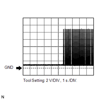
|
Tester Connection |
D22-13 (EFIO) - D22-16 (GND) |
|
Tool Setting |
2 V/DIV., 1 s./DIV. |
|
Condition |
Ignition switch ON |
(4) Waveform 4 (Reference)
.png)
|
Tester Connection |
D22-12 (EFII) - D22-16 (GND) |
|
Tool Setting |
5 V/DIV., 500 ms/DIV. |
|
Condition |
Within 3 seconds after starter operates and initial combustion occurs, or within 3seconds after ignition switch first turned on (IG) after battery disconnected and connected. |
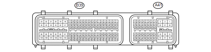
3. CHECK ECM (for 2GR-FE)
(a) The values listed under "Specified Condition" are reference values. Because waterproof connectors are used for ECM, inspections cannot be performed with the connectors connected.
|
Tester Connection |
Wiring Color |
Terminal Description |
Condition |
Specified Condition |
|---|---|---|---|---|
|
B39-81 (E1) - Body ground |
W - Body ground |
Ground |
Always |
Below 1 Ω |
|
A41-29 (IMO) - B39-81 (E1) |
BR - W |
Transponder key ECU output signal |
Ignition switch off |
11 to 14 V |
|
A41-29 (IMO) - B39-81 (E1) |
BR - W |
Transponder key ECU output signal |
Within 3 seconds after starter operates and initial combustion occurs, or within 3seconds after ignition switch first turned on (IG) after battery disconnected and connected. |
Pulse generation (See waveform 1) |
|
A41-40 (IMI) - B39-81 (E1) |
G - W |
Transponder key ECU input signal |
Ignition switch off |
Below 1 V |
|
A41-40 (IMI) - B39-81 (E1) |
G - W |
Transponder key ECU input signal |
Ignition switch ON |
Pulse generation (See waveform 2) |
(b) Inspect using an oscilloscope.
(1) Waveform 1 (Reference)
|
Tester Connection |
A41-29 (IMO) - B39-81 (E1) |
|
Tool Setting |
5 V/DIV., 500 ms/DIV. |
|
Condition |
Within 3 seconds after starter operates and initial combustion occurs, or within 3seconds after ignition switch first turned on (IG) after battery disconnected and connected. |
(2) Waveform 2 (Reference)
|
Tester Connection |
A41-40 (IMI) - B39-81 (E1) |
|
Tool Setting |
2 V/DIV., 1 s./DIV. |
|
Condition |
Ignition switch ON |
4. CHECK ECM (for 1AR-FE)
(a) The values listed under "Specified Condition" are reference values. Because waterproof connectors are used for ECM, inspections cannot be performed with the connectors connected.
.png)
|
Tester Connection |
Wiring Color |
Terminal Description |
Condition |
Specified Condition |
|---|---|---|---|---|
|
B58-104 (E1) - Body ground |
BR - Body ground |
Ground |
Always |
Below 1 Ω |
|
A49-10 (IMO) - B58-104 (E1) |
BR - BR |
Certification ECU (smart key ECU assembly) output signal |
Ignition switch off |
11 to 14 V |
|
A49-10 (IMO) - B58-104 (E1) |
BR - BR |
Certification ECU (smart key ECU assembly) output signal |
Within 3 seconds after the starter operates and initial combustion occurs, or within 3 seconds after Ignition switch first turned on (IG) after battery disconnected and connected |
Pulse generation (See waveform 1) |
|
A49-11 (IMI) - B58-104 (E1) |
G - BR |
Certification ECU (smart key ECU assembly) input signal |
Ignition switch off |
11 to 14 V |
|
A49-11 (IMI) - B58-104 (E1) |
G - BR |
Certification ECU (smart key ECU assembly) input signal |
Ignition switch on (IG) |
Pulse generation (See waveform 2) |
(b) Inspect using an oscilloscope.
(1) Waveform 1 (Reference)
|
Tester Connection |
A49-10 (IMO) - B58-104 (E1) |
|
Tool Setting |
5 V/DIV., 500 ms/DIV. |
|
Condition |
Within 3 seconds after starter operates and initial combustion occurs, or within 3seconds after ignition switch first turned on (IG) after battery disconnected and connected. |
(2) Waveform 2 (Reference)
|
Tester Connection |
A49-11 (IMI) - B58-104 (E1) |
|
Tool Setting |
2 V/DIV., 1 s./DIV. |
|
Condition |
Ignition switch ON |
5. ACCESSORY METER ASSEMBLY
(a) Disconnect the F2 accessory meter assembly connector.
.png)
(b) Measure the voltage and resistance according to the value(s) in the table below.
HINT:
Measure the values on the wire harness side with connector disconnected.
|
Terminal No. (Symbol) |
Wiring Color |
Terminal Description |
Condition |
Specified Condition |
|---|---|---|---|---|
|
F2-1 (B) - Body ground |
P - Body ground |
Battery |
Always |
11 to 14 V |
|
F2-12 (E) - Body ground |
B - Body ground |
Ground |
Always |
Below 1 Ω |
If the result is not as specified, there may be a malfunction in the wire harness.
(c) Reconnect the F2 accessory meter assembly connector.
(d) Measure the voltage according to the value(s) in the table below.
|
Terminal No. (Symbol) |
Wiring Color |
Terminal Description |
Condition |
Specified Condition |
|---|---|---|---|---|
|
F2-14 (LP) - Body ground |
Y - Body ground |
Security indicator light signal |
Ignition switch ON, security indicator light off |
11 to 14 V |
|
F2-14 (LP) - Body ground |
Y - Body ground |
Security indicator light signal |
Ignition switch off, security indicator light blinks |
Alternating between 11 to 14 V and below 1 V |
If the result is not as specified, the accessory meter assembly may have a malfunction.
 Diagnosis System
DIAGNOSIS SYSTEM
1. DESCRIPTION
(a) The transponder key ECU assembly controls the vehicle's immobiliser system
functions. Immobiliser system data and Diagnostic Trouble Code (DTC) can be read ...
 Dtc Check / Clear
DTC CHECK / CLEAR
1. CHECK FOR TRANSPONDER KEY ECU DTC
(a) Connect the Techstream to the DLC3.
(b) Turn the ignition switch to ON.
(c) Turn the Techstream on.
(d) Enter the following menus: Body ...
Other materials about Toyota Venza:
Inspection
INSPECTION
PROCEDURE
1. INSPECT FRONT OIL PUMP AND GEAR BODY SUB-ASSEMBLY
(a) Turn the drive gear with 2 screwdrivers and make sure that it rotates
smoothly.
NOTICE:
Be careful not to damage the oil seal lip.
...
Ambient Temperature Sensor
Components
COMPONENTS
ILLUSTRATION
Inspection
INSPECTION
PROCEDURE
1. INSPECT AMBIENT TEMPERATURE SENSOR
(a) Measure the resistance according to the value(s) in the table below.
Standard Resistance:
Tester Connection
C ...
Window Defogger Wire
On-vehicle Inspection
ON-VEHICLE INSPECTION
PROCEDURE
1. CHECK REAR WINDOW DEFOGGER SYSTEM OPERATION
(a) When the ignition switch is turned to ON and the rear window defogger switch
is pressed, check that the rear window defogger system operates.
2. I ...

0.1577