Toyota Venza: Ambient Temperature Sensor
Components
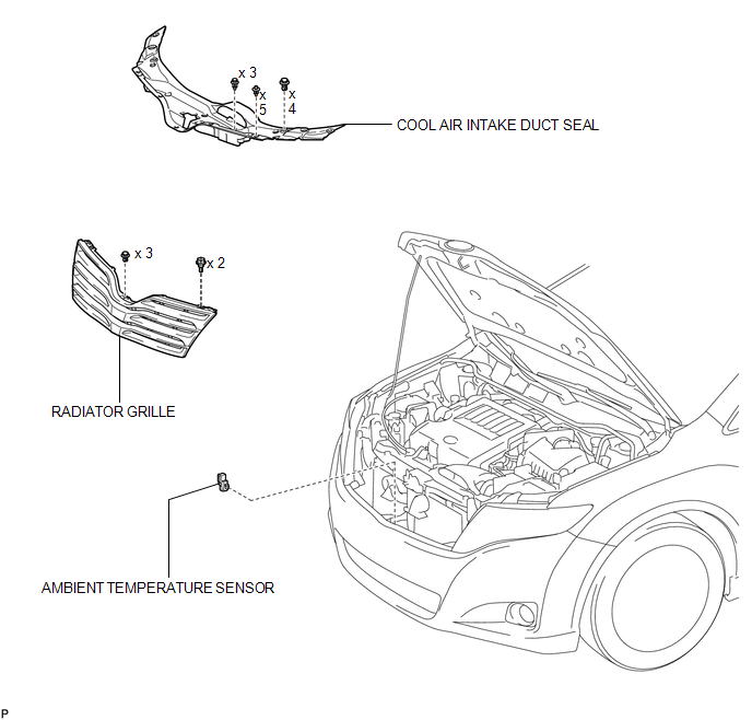
COMPONENTS
ILLUSTRATION
Inspection
INSPECTION
PROCEDURE
1. INSPECT AMBIENT TEMPERATURE SENSOR
(a) Measure the resistance according to the value(s) in the table below.
.png)
.png)
Standard Resistance:
|
Tester Connection |
Condition |
Specified Condition |
|---|---|---|
|
1 - 2 |
10°C (50°F) |
3.00 to 3.73 kΩ |
|
1 - 2 |
15°C (59°F) |
2.45 to 2.88 kΩ |
|
1 - 2 |
20°C (68°F) |
1.95 to 2.30 kΩ |
|
1 - 2 |
25°C (77°F) |
1.60 to 1.80 kΩ |
|
1 - 2 |
30°C (86°F) |
1.28 to 1.47 kΩ |
|
1 - 2 |
35°C (95°F) |
1.00 to 1.22 kΩ |
|
1 - 2 |
40°C (104°F) |
0.80 to 1.00 kΩ |
|
1 - 2 |
45°C (113°F) |
0.65 to 0.85 kΩ |
|
1 - 2 |
50°C (122°F) |
0.50 to 0.70 kΩ |
|
1 - 2 |
55°C (131°F) |
0.44 to 0.60 kΩ |
|
1 - 2 |
60°C (140°F) |
0.36 to 0.50 kΩ |
NOTICE:
- Hold the sensor only by its connector. Touching the sensor may change the resistance value.
- When measuring, the sensor temperature must be the same as the ambient temperature.
HINT:
As the temperature increases, the resistance decreases (see the graph).
If the resistance is not as specified, replace the ambient temperature sensor.
Text in Illustration|
*1 |
Component without harness connected (Ambient Temperature Sensor) |
|
*2 |
Sensing Portion |
Removal
REMOVAL
PROCEDURE
1. DISCONNECT CABLE FROM NEGATIVE BATTERY TERMINAL
NOTICE:
When disconnecting the cable, some systems need to be initialized after the cable
is reconnected (See page .gif) ).
).
2. REMOVE COOL AIR INTAKE DUCT SEAL
3. REMOVE RADIATOR GRILLE
4. REMOVE AMBIENT TEMPERATURE SENSOR
|
(a) Disconnect the connector. |
|
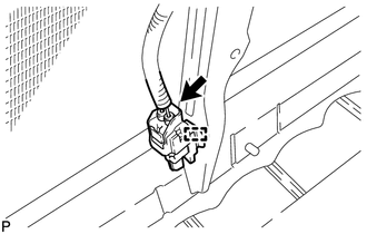
(b) Disengage the clamp to remove the ambient temperature sensor.
Installation
INSTALLATION
PROCEDURE
1. INSTALL AMBIENT TEMPERATURE SENSOR
|
(a) Engage the clamp to install the ambient temperature sensor. |
|
.png)
(b) Connect the connector.
2. INSTALL RADIATOR GRILLE
.gif)
3. INSTALL COOL AIR INTAKE DUCT SEAL
4. CONNECT CABLE TO NEGATIVE BATTERY TERMINAL
NOTICE:
When disconnecting the cable, some systems need to be initialized after the cable
is reconnected (See page ).
 Installation
INSTALLATION
PROCEDURE
1. INSTALL AIR CONDITIONING UNIT ASSEMBLY
(a) Install the air conditioning unit assembly with the 3 nuts.
Torque:
9.8 N·m {100 kgf·cm, 87 in·lbf}
NOTICE:
Tighten th ...
 Blower Unit
...
Other materials about Toyota Venza:
On-vehicle Inspection
ON-VEHICLE INSPECTION
PROCEDURE
1. INSPECT PARK/NEUTRAL POSITION SWITCH ASSEMBLY OPERATION
(a) Apply the parking brake.
(b) Turn the ignition switch to ON.
(c) Depress the brake pedal and check that the engine starts when the shift lever
is in N or P, b ...
Initialization
INITIALIZATION
1. RESET BACK DOOR CLOSE POSITION
NOTICE:
Perform initialization of the power back door system (power back door ECU initialization)
if one of the following is performed:
The cable is disconnected from the negative (-) battery termin ...
No Answer-Back
DESCRIPTION
In some cases, wireless door lock control functions are normal but the hazard
warning light and/or wireless door lock buzzer answer-back function(s) does not
operate. In such cases, the main body ECU (driver side junction block assembly)
haz ...

0.1152