Toyota Venza: Inspection
INSPECTION
PROCEDURE
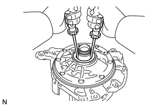
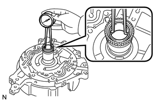
1. INSPECT FRONT OIL PUMP AND GEAR BODY SUB-ASSEMBLY
|
(a) Turn the drive gear with 2 screwdrivers and make sure that it rotates smoothly. NOTICE: Be careful not to damage the oil seal lip. |
|
2. INSPECT CLEARANCE OF FRONT OIL PUMP AND GEAR BODY SUB-ASSEMBLY
|
(a) Push the driven gear to one side of the body. |
|
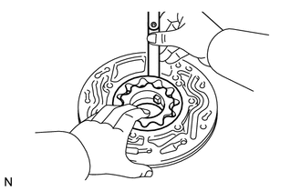
(b) Using a feeler gauge, measure the clearance.
Standard clearance:
0.08 to 0.15 mm (0.00315 to 0.00590 in.)
Maximum clearance:
0.15 mm (0.00590 in.)
If the clearance is greater than the maximum, replace the oil pump body sub-assembly.
|
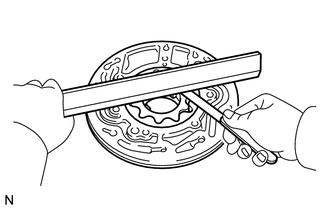
(c) Using a straightedge and feeler gauge, measure the side clearance of both gears. Standard side clearance: 0.025 to 0.04 mm (0.000984 to 0.00157 in.) Maximum side clearance: 0.04 mm (0.00157 in.) Drive Gear Thickness
|
|
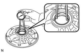
3. INSPECT FRONT OIL PUMP AND GEAR BODY SUB-ASSEMBLY
|
(a) Using a dial indicator, measure the inside diameter of the oil pump body bushing. Standard inside diameter: 43.113 to 43.138 mm (1.6974 to 1.6983 in.) Maximum inside diameter: 43.188 mm (1.7003 in.) If the inside diameter is greater than the maximum, replace the oil pump body sub-assembly. |
|
4. INSPECT STATOR SHAFT ASSEMBLY
|
(a) Using a dial indicator, measure the inside diameter of the oil pump body bushing. Standard inside diameter: 22.500 to 22.526 mm (0.8858 to 0.8868 in.) Maximum inside diameter: 22.570 mm (0.8886 in.) If the inside diameter is greater than the maximum, replace the oil pump body sub-assembly. |
|
 Disassembly
DISASSEMBLY
PROCEDURE
1. INSPECT FRONT OIL PUMP AND GEAR BODY SUB-ASSEMBLY
2. REMOVE STATOR SHAFT ASSEMBLY
(a) Using a "TORX" wrench (T30), remove the 16 bolts and stator s ...
 Reassembly
REASSEMBLY
PROCEDURE
1. INSTALL FRONT OIL PUMP OIL SEAL
(a) Using SST and a hammer, install a new oil seal to the oil pump body.
SST: 09350-32014
09351-32140
Oil seal driven in ...
Other materials about Toyota Venza:
Starter Relay Circuit High (P0617)
DESCRIPTION
While the engine is being cranked, battery voltage is applied to terminal STA
of the TCM.
If the TCM detects the Starter Control (STA) signal while the vehicle is being
driven, it determines that there is a malfunction in the STA circuit. The ...
Terminals Of Ecu
TERMINALS OF ECU
1. CHECK MAIN BODY ECU (DRIVER SIDE JUNCTION BLOCK ASSEMBLY)
(a) Disconnect the main body ECU (driver side junction block assembly) connectors.
(b) Measure the resistance and voltage according to the value(s) in the table
below.
...
Inspection
INSPECTION
PROCEDURE
1. INSPECT FRONT SEAT CUSHION HEATER LH
(a) Check the seat cushion heater.
(1) Apply battery voltage and check the seat cushion heater.
OK:
Measurement Condition
Condition
...

0.136