Toyota Venza: System Diagram
SYSTEM DIAGRAM
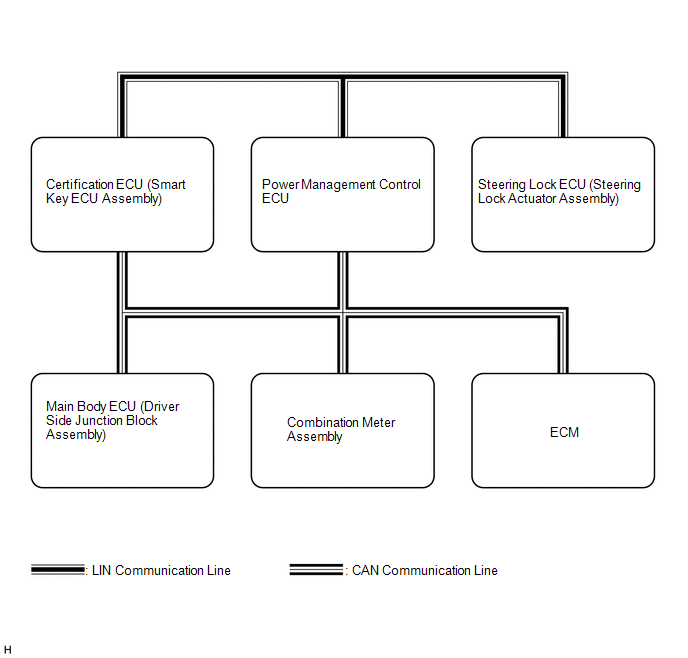
 Communication Table
|
Transmitting ECU (Transmitter) |
Receiving ECU |
Signal |
Communication Method |
|---|---|---|---|
|
Main body ECU (Driver side junction block assembly) |
Certification ECU (Smart key ECU assembly) |
Courtesy light switch signal |
CAN |
|
Door lock output signal |
|||
|
Back door output request signal |
|||
|
Door lock position switch signal |
|||
|
Driver door key operated switch signal |
|||
|
Certification ECU (Smart key ECU assembly) |
Main body ECU (Driver side junction block assembly) |
Illumination light request signal |
CAN |
|
Door lock/unlock request signal |
|||
|
Certification ECU (Smart key ECU assembly) |
Combination meter assembly |
Meter buzzer single tone request signal |
CAN |
|
Meter buzzer intermittent tone request signal |
|||
|
Meter buzzer continuous tone request signal |
|||
|
Key loss warning signal |
|||
|
Low key battery warning signal |
|||
|
Steering lock malfunction warning signal |
|||
|
Steering lock not-released warning signal |
|||
|
Shift position warning signal |
|||
|
Emergency operation support display request signal |
|||
|
Engine start method display request signal |
|||
|
Combination meter assembly |
|
Vehicle speed signal |
CAN |
|
Steering lock ECU (Steering lock actuator assembly) |
Certification ECU (Smart key ECU assembly) |
Encryption code signal |
LIN |
|
Encryption code finish signal |
|||
|
Encryption calculate fixed number memory requirement signal |
|||
|
During entry control signal |
 Parts Location
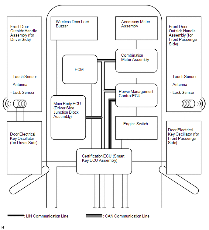
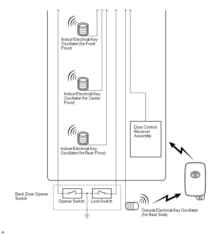
PARTS LOCATION
ILLUSTRATION
ILLUSTRATION
ILLUSTRATION
ILLUSTRATION
...
 System Description
SYSTEM DESCRIPTION
CAUTION:
If using a pacemaker, be sure to read the manual of the pacemaker before using
the key, as the radio waves of the key may affect the pacemaker.
1. SMART KEY SYSTEM DES ...
Other materials about Toyota Venza:
Replacement
REPLACEMENT
PROCEDURE
1. REPLACE RING PIN
NOTICE:
It is not necessary to remove the ring pin unless it is being replaced.
(a) Remove the 12 ring pins.
(b) Using a plastic-faced hammer, install 12 new ring pins.
Standard Protrusion Height:
...
How To Proceed With Troubleshooting
CAUTION / NOTICE / HINT
HINT:
Use the following procedure to troubleshoot the engine immobiliser system.
*: Using the Techstream.
PROCEDURE
1.
VEHICLE BROUGHT TO WORKSHOP
NEXT
...
Installation
INSTALLATION
PROCEDURE
1. INSTALL REAR COMBINATION LIGHT ASSEMBLY
(a) Engage the guide and 2 pins, and install the rear combination light
assembly as shown in the illustration.
Text in Illustration
*1
P ...

0.1338