Toyota Venza: Parts Location
PARTS LOCATION
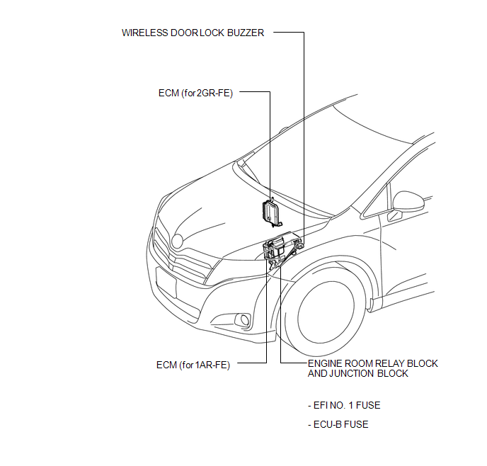
ILLUSTRATION
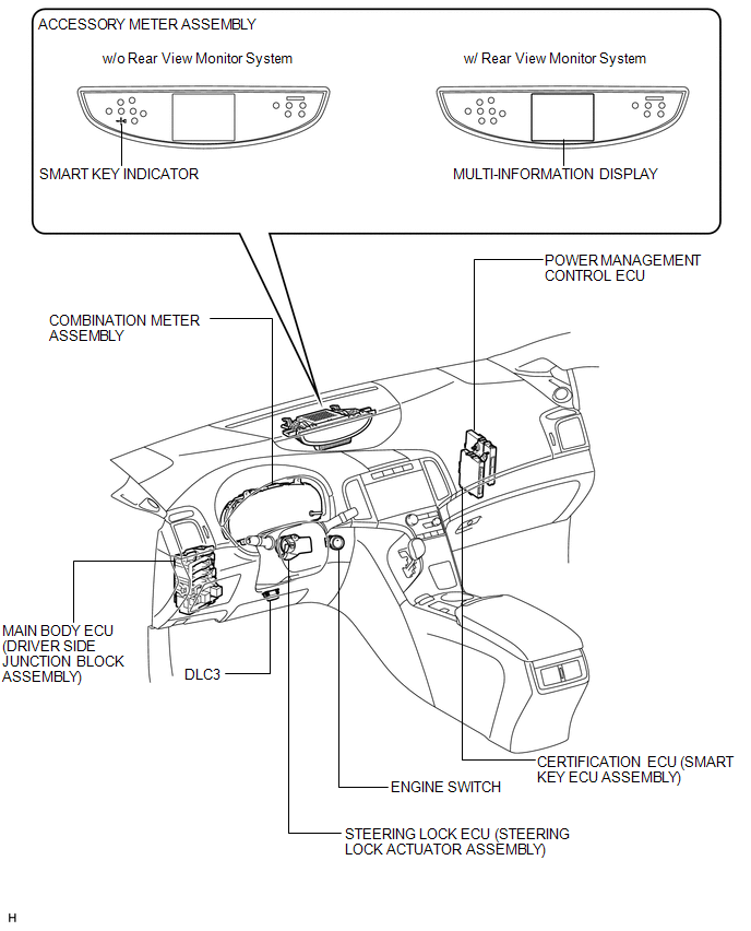
ILLUSTRATION
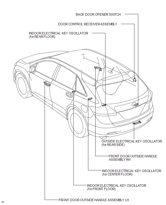
ILLUSTRATION
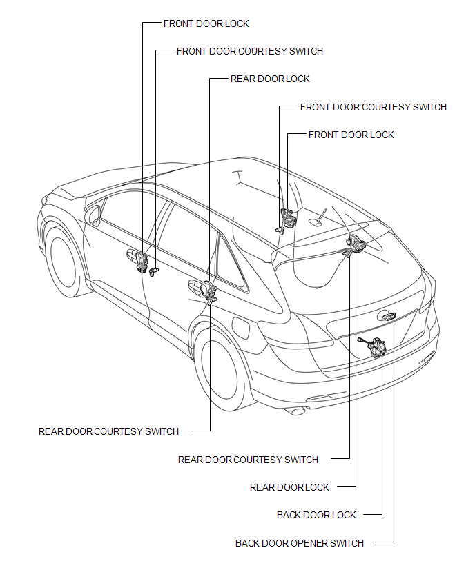
ILLUSTRATION
 Precaution
PRECAUTION
1. PRECAUTION FOR DISCONNECTING CABLE FROM NEGATIVE BATTERY TERMINAL
NOTICE:
When disconnecting the cable from the negative (-) battery terminal, initialize
the following system after ...
 System Diagram
SYSTEM DIAGRAM
Communication Table
Transmitting ECU (Transmitter)
Receiving ECU
Signal
Communication Method
Main body ECU (Driver si ...
Other materials about Toyota Venza:
Precaution
PRECAUTION
NOTICE:
When disconnecting the cable from the negative (-) battery terminal, initialize
the following systems after the cable is reconnected.
System Name
See Procedure
Back Door Closer System
...
Rear window defogger
Clear the rear window using the defogger.
On/off
The defogger will automatically turn off after 15 or 60 minutes.
This operation time changes according to the ambient temperature and vehicle
speed.
Pressing the switch again also turns the defogger off. ...
Disassembly
DISASSEMBLY
PROCEDURE
1. REMOVE INTAKE VALVE
(a) Using SST and wooden blocks, compress the compression spring and
remove the valve spring retainer locks.
SST: 09202-70020
09202-00010
(b) R ...

0.1349