Toyota Venza: Reassembly
REASSEMBLY
CAUTION / NOTICE / HINT
NOTICE:
When using a vise, do not overtighten it.
PROCEDURE
1. INSTALL STEERING LOCK ACTUATOR ASSEMBLY (w/ Smart Key System)
(a) Secure the steering column assembly in a vise.
|
(b) Temporarily install the steering lock actuator assembly to the steering column assembly with a new tapered-head bolt. NOTICE: Be sure to use a new tapered-head bolt. |
|
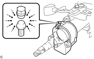
(c) Tighten the tapered-head bolt until the bolt heads break off.
2. INSTALL UNLOCK WARNING SWITCH ASSEMBLY (w/o Smart Key System)
|
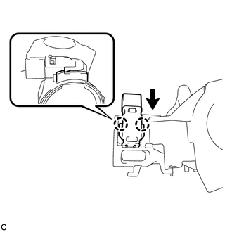
(a) Engage the 2 claws to install the unlock warning switch onto the steering column upper bracket. HINT: Slide the unlock warning switch in the direction shown by the arrow in the illustration to install it. |
|
3. INSTALL IGNITION SWITCH LOCK CYLINDER ASSEMBLY (w/o Smart Key System)
|
(a) Make sure that the ignition switch lock cylinder assembly is in the ACC position. |
|
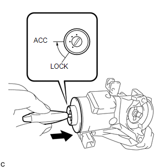
(b) Install the ignition switch lock cylinder assembly to the steering lock sub-assembly.
(c) Make sure that the ignition switch lock cylinder assembly is securely installed.
4. INSTALL SOLENOID WIRE (w/o Smart Key System)
|
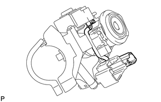
(a) Install the solenoid wire to the steering column upper bracket. |
|
.png)
5. INSTALL KEY INTER LOCK SOLENOID (w/o Smart Key System)
|
(a) Connect the solenoid wire connector to the key interlock solenoid. |
|
.png)
|
(b) Install the key interlock solenoid to the steering column upper bracket with the 2 screws. |
|
.png)
6. INSTALL IGNITION OR STARTER SWITCH ASSEMBLY (w/o Smart Key System)
|
(a) Install the ignition or starter switch assembly to the steering column upper bracket with the 2 screws. |
|
.png)
|
(b) Install the solenoid wire connector to the ignition or starter switch assembly. |
|
.png)
|
(c) Make sure that the solenoid wire runs securely through the gap of the steering column upper bracket as shown in the illustration. |
|
7. INSPECT STEERING LOCK OPERATION (w/o Smart Key System)
.gif)
8. INSTALL STEERING COLUMN UPPER WITH SWITCH BRACKET ASSEMBLY (w/o Smart Key System)
(a) Secure the steering column assembly in a vise.
|
(b) Temporarily install the steering column upper with switch bracket assembly to the steering column assembly with a new tapered-head bolt. NOTICE: Be sure to use a new tapered-head bolt. |
|

(c) Tighten the tapered-head bolt until the bolt heads break off.
 Inspection
INSPECTION
PROCEDURE
1. INSPECT PRELOAD
(a) Secure the steering column assembly in a vise.
Text in Illustration
*1
Service Nut
...
 Installation
INSTALLATION
PROCEDURE
1. INSTALL STEERING INTERMEDIATE SHAFT ASSEMBLY
(a) Align the matchmarks on the steering intermediate shaft assembly
and the steering column assembly.
Text ...
Other materials about Toyota Venza:
How To Proceed With Troubleshooting
CAUTION / NOTICE / HINT
HINT:
Use this procedure to troubleshoot the theft deterrent system.
*: Use the Techstream.
PROCEDURE
1.
VEHICLE BROUGHT TO WORKSHOP
NEXT
...
Components
COMPONENTS
ILLUSTRATION
ILLUSTRATION
ILLUSTRATION
ILLUSTRATION
ILLUSTRATION
ILLUSTRATION
ILLUSTRATION
ILLUSTRATION
ILLUSTRATION
...
How To Proceed With Troubleshooting
CAUTION / NOTICE / HINT
HINT:
Use the following procedure to troubleshoot the windshield deicer system.
PROCEDURE
1.
VEHICLE BROUGHT TO WORKSHOP
NEXT
...

0.1573