Toyota Venza: System Diagram
SYSTEM DIAGRAM
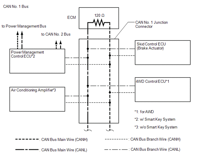
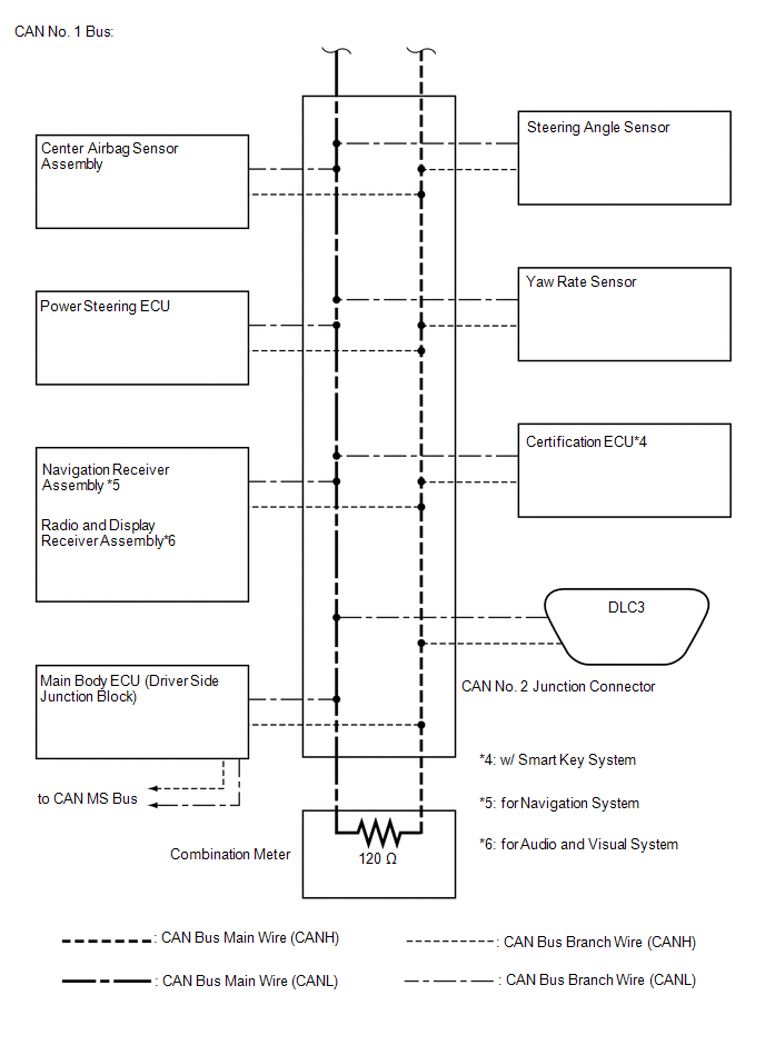
1. CAN NO. 1 BUS
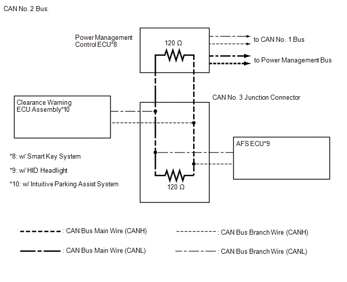
2. CAN NO. 2 BUS
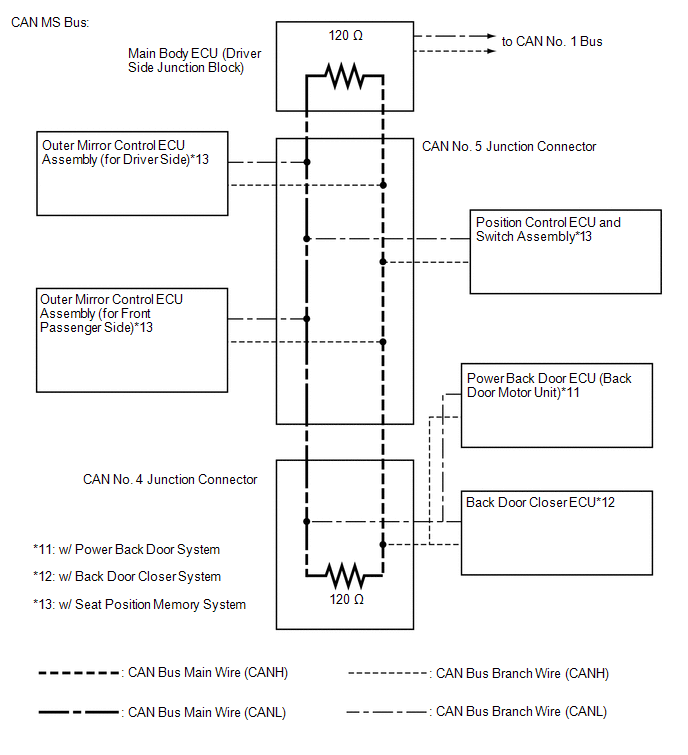
3. CAN MS BUS
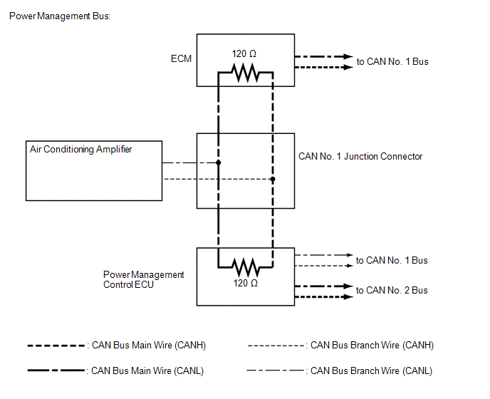
4. POWER MANAGEMENT BUS (w/ Smart Key System)
 Precaution
PRECAUTION
1. PRECAUTION FOR DISCONNECTING BATTERY CABLE
NOTICE:
When disconnecting the cable from the negative (-) battery terminal, initialize
the following systems after the cable is reconnect ...
 How To Proceed With Troubleshooting
CAUTION / NOTICE / HINT
PRECAUTIONS WHEN TROUBLESHOOTING
NOTICE:
DTCs for the CAN communication system are as follows: U0073, U0100,
U0101, U0123, U0124, U0126, U0129, U0131, U0142, U01 ...
Other materials about Toyota Venza:
Power Mirrors do not Return to Memorized Position
SYSTEM DESCRIPTION
If either the M1 or M2 seat memory switch is pressed, the outer mirror control
ECU assembly (driver door) detects the seat memory switch status and sends the switch
signal to the main body ECU (driver side junction block assembly) via C ...
Jam Protection Function does not Operate
DESCRIPTION
This symptom may occur for any of the windows.
The jam protection function operates within a specified range during the manual
up or auto up operation.
CAUTION / NOTICE / HINT
NOTICE:
The power window control system uses a multiplex ...
Compressor Solenoid Circuit (B1451/51)
DESCRIPTION
In this circuit, the A/C compressor receives a refrigerant compression demand
signal from the A/C amplifier.
Based on this signal, the A/C compressor changes the amount of compressor output.
DTC No.
DTC Detection Conditio ...

0.1345