Toyota Venza: Precaution
PRECAUTION
1. PRECAUTION FOR DISCONNECTING BATTERY CABLE
NOTICE:
When disconnecting the cable from the negative (-) battery terminal, initialize the following systems after the cable is reconnected.
|
System |
See Procedure |
|---|---|
|
Back door closer system |
|
|
Power back door system |
|
2. PRECAUTIONS FOR STEERING SYSTEM HANDLING
(a) Be careful when replacing parts. Incorrect replacement could affect the performance of the steering system and result in hazardous driving.
3. PRECAUTIONS FOR SRS AIRBAG SYSTEM HANDLING
(a) This vehicle is equipped with an Supplemental Restraint System (SRS) which
includes parts such as airbags for the driver and front passenger. Failure to carry
out service operations in the correct sequence could cause unexpected SRS deployment
during servicing and may cause a serious accident. Before servicing (including removal
or installation of parts, inspection or replacement), be sure to read the precaution
for the SRS (See page .gif) ).
).
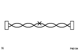
4. BUS WIRE REPAIR
(a) After repairing a bus wire with solder, wrap the repaired part with electrical tape.
NOTICE:
- The CANL bus wire and CANH bus wire must be installed together at all times.
- When installing, make sure that these wires are twisted, because CAN bus wires are likely to be influenced by electrical noise if the bus wires are not twisted.
- The difference in length between the CANL bus wire and CANH bus wire should be 100 mm (3.937 in.) or less.
- Leave approximately 80 mm (3.150 in.) loose in the twisted wires around the connector.
(b) Do not use bypass wiring between connectors.
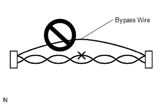
NOTICE:
The ability of the twisted bus wires to resist interference will be lost if bypass wiring is used.
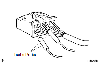
5. CONNECTOR HANDLING
(a) When checking resistance with a tester, insert the tester probes from the backside (harness side) of the connector.
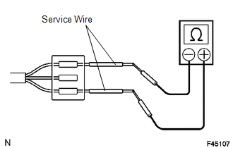
(b) Use service wires to check the connector if it is impossible to check continuity from the rear of the connector.
6. PRECAUTIONS FOR INSPECTING OR REPLACING CAN JUNCTION CONNECTOR
(a) If the CAN junction connector is removed from the vehicle for inspection or replacement, make sure to install the CAN junction connector and all wire harnesses to their original locations with tape and the clamps.
 Parts Location
PARTS LOCATION
ILLUSTRATION
ILLUSTRATION
ILLUSTRATION
ILLUSTRATION
...
 System Diagram
SYSTEM DIAGRAM
1. CAN NO. 1 BUS
2. CAN NO. 2 BUS
3. CAN MS BUS
4. POWER MANAGEMENT BUS (w/ Smart Key System)
...
Other materials about Toyota Venza:
Inspection
INSPECTION
PROCEDURE
1. INSPECT INTAKE AIR CONTROL VALVE (for ACIS)
(a) Inspect the diaphragm.
(1) Using a vacuum pump, apply a vacuum of 60 kPa (450 mmHg, 17.7 in.Hg)
or higher to the diaphragm chamber. Wait for 1 minute and check that the ...
Screen Flicker or Color Distortion
PROCEDURE
1.
CHECK DISPLAY SETTING
(a) Reset display settings (contrast, brightness) and check that the screen appears
normal.
OK:
The display returns to normal.
OK
END
NG
...
Installation
INSTALLATION
CAUTION / NOTICE / HINT
NOTICE:
When disconnecting the steering intermediate shaft assembly and pinion shaft
of steering gear assembly, be sure to place matchmarks before servicing.
PROCEDURE
1. INSTALL TIE ROD ASSEMBLY LH
(a) I ...

0.1284