Toyota Venza: License Plate Light Assembly
Components
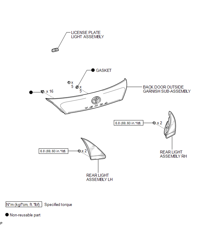
COMPONENTS
ILLUSTRATION
.png)
ILLUSTRATION
Installation
INSTALLATION
PROCEDURE
1. INSTALL LICENSE PLATE LIGHT ASSEMBLY
|
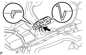
(a) Engage the 2 claws to install the license plate light assembly. |
|
(b) Connect the connector.
2. INSTALL BACK DOOR OUTSIDE GARNISH SUB-ASSEMBLY
.gif)
3. INSTALL REAR LIGHT ASSEMBLY LH
4. INSTALL REAR LIGHT ASSEMBLY RH
HINT:
Use the same procedure for the RH side and LH side.
5. INSTALL REAR WIPER MOTOR AND BRACKET ASSEMBLY
6. INSTALL REAR WIPER MOTOR GROMMET
7. INSTALL REAR WIPER ARM AND BLADE ASSEMBLY
8. INSTALL REAR WIPER ARM HEAD CAP
9. INSTALL BACK DOOR PANEL TRIM ASSEMBLY
Removal
REMOVAL
PROCEDURE
1. REMOVE BACK DOOR PANEL TRIM ASSEMBLY
.gif)
2. REMOVE REAR WIPER ARM HEAD CAP
3. REMOVE REAR WIPER ARM AND BLADE ASSEMBLY
4. REMOVE REAR WIPER MOTOR GROMMET
5. REMOVE REAR WIPER MOTOR AND BRACKET ASSEMBLY
6. REMOVE REAR LIGHT ASSEMBLY LH
7. REMOVE REAR LIGHT ASSEMBLY RH
HINT:
Use the same procedure for the RH side and LH side.
8. REMOVE BACK DOOR OUTSIDE GARNISH SUB-ASSEMBLY
9. REMOVE LICENSE PLATE LIGHT ASSEMBLY
|
(a) Disconnect the connector. |
|
.png)
(b) Disengage the 2 claws and remove the license plate light assembly.
 High Mounted Stop Light Assembly
Components
COMPONENTS
ILLUSTRATION
Removal
REMOVAL
PROCEDURE
1. REMOVE CENTER STOP LIGHT ASSEMBLY
(a) Using a short screwdriver, remove the 2 screws.
...
 Lighting System
...
Other materials about Toyota Venza:
Key-off Operation Function Operates even if Operating Conditions are not Satisfied
DESCRIPTION
When the front doors are closed, each power window regulator motor assembly
can control its power window operation for approximately 45 seconds after
the ignition switch is turned from ON to off by receiving operation permission
...
P/W Master Switch Communication Stop (B1206)
DESCRIPTION
This DTC is stored when LIN communication between the multiplex network master
switch assembly and main body ECU (driver side junction block assembly) stops for
more than 10 seconds.
DTC No.
DTC Detection Condition
...
TC and CG Terminal Circuit
DESCRIPTION
Connecting terminals TC and CG of the DLC3 causes the system to enter self-diagnostic
mode. If a malfunction is present, the MIL will blink.
HINT:
When a particular warning light remains blinking, a ground short in the wiring
of terminal TC ...

0.1148