Toyota Venza: System Description
SYSTEM DESCRIPTION
1. DESCRIPTION OF SYSTEM
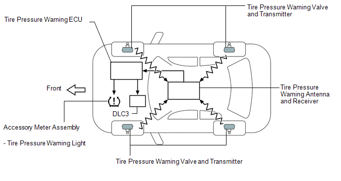
(a) Each tire pressure warning valve and transmitter is equipped with a tire pressure sensor and a transmitter and is installed in each tire and wheel assembly. The sensor measures the tire pressure. The measured value and transmitter ID are transmitted to the tire pressure warning antenna and receiver on the body as radio waves and then sent to the tire pressure warning ECU from the tire pressure warning antenna and receiver. If the transmitter ID has already been registered, the ECU compares the measured air pressure value with the standard value. When the value is less than the standard value registered in the tire pressure warning ECU, the warning light on the accessory meter comes on.
2. INITIAL CHECK
(a) After the ignition switch is turned to ON, the tire pressure warning light comes on for 3 seconds and then goes off.
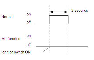
HINT:
If the warning light does not come on for 3 seconds, troubleshoot the tire pressure
warning light circuit (See page .gif) ).
).
3. WHEN TIRE PRESSURE WARNING LIGHT IS LIT
(a) When the tire pressure warning light does not go off, or when it comes on while driving, check the tire pressure. If the tire pressure warning light comes on within several hours of adjusting the tire pressure, the tire may have a slow leak.
(b) Under the following conditions, the system may not function properly:
(1) The system will not function properly in the following conditions:
(When the condition becomes normal, the system will work properly.)
- If tires not equipped with tire pressure warning valve and transmitters are used.
- If the ID code on the tire pressure warning valve and transmitters is not registered in the tire pressure warning ECU.
- If the tire inflation pressure is absolute pressure: 600 kPa (6.0 kgf/cm2, 87 psi) or more; relative pressure: 500 kPa (5.0 kgf/cm2, 73 psi) or more.
- If the tire pressure warning valve and transmitter battery voltage drops (battery life: 10 years).
(2) The system may not function properly in the following conditions:
(When the condition becomes normal, the system will work properly.)
- If electronic devices or facilities using similar radio wave frequencies are nearby.
- If a radio set at similar frequencies is used in the vehicle.
- If a window tint that affects the radio wave signal is installed.
- If there is a lot of snow or ice on the vehicle, in particular around the wheels or wheel housings.
- If non-genuine wheels are used.
- If tire chains are used.
(c) After removing and installing the ECU or a sensor, check for DTCs.
4. FUNCTION OF COMPONENTS
|
Component |
Function |
|---|---|
|
Tire pressure warning valve and transmitter |
Combined as a single unit with a tire valve, it measures tire pressure and temperature and transmits an ID number for identification. Has a built-in battery. |
|
Tire pressure warning antenna and receiver |
Receives signals from the transmitters and transmits them to the tire pressure warning ECU. |
|
Tire pressure warning ECU |
Receives a signal from the receiver and identifies it as vehicle's own signal. If the measured value is equal to or lower than the specified value, it transmits a signal to illuminate the tire pressure warning light on the accessory meter. |
|
Tire pressure warning light |
Located in the accessory meter, it informs the driver of low tire pressure and system failures. |
 How To Proceed With Troubleshooting
CAUTION / NOTICE / HINT
HINT:
Use the following procedures to troubleshoot the tire pressure warning
system.
*: Use the Techstream.
PROCEDURE
1.
VEHICL ...
 Registration
REGISTRATION
PROCEDURE
1. DESCRIPTION OF CODE REGISTRATION
It is necessary to register the transmitter IDs in the tire pressure warning
ECU when replacing a tire pressure warning valve and transm ...
Other materials about Toyota Venza:
Parking Brake Switch Circuit
DESCRIPTION
The main body ECU (driver side junction block assembly) detects the condition
of the parking brake switch.
WIRING DIAGRAM
PROCEDURE
1.
READ VALUE USING TECHSTREAM
(a) Connect the Techstream to the DLC3.
(b) ...
Installation
INSTALLATION
PROCEDURE
1. INSTALL FRONT DOOR OUTSIDE HANDLE ASSEMBLY
(a) Insert the front end of the front door outside handle assembly into
the front door outside handle frame.
(b) Insert the r ...
Engine Immobiliser System Malfunction (B2799)
DESCRIPTION
This DTC is stored when one of the following occurs: 1) the ECM detects an error
in its own communication with the certification ECU (smart key ECU assembly); 2)
the ECM detects an error in the communication lines; or 3) the ECU communication ...

0.1193