Toyota Venza: Removal
REMOVAL
PROCEDURE
1. DISCONNECT CABLE FROM NEGATIVE BATTERY TERMINAL
NOTICE:
When disconnecting the cable, some systems need to be initialized after the cable
is reconnected (See page .gif) ).
).
2. REMOVE RADIATOR ASSEMBLY
HINT:
See page
3. REMOVE V-RIBBED BELT
HINT:
See page
4. REMOVE GENERATOR ASSEMBLY
|
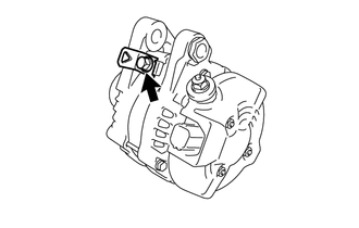
(a) Remove the terminal cap. |
|
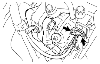
(b) Remove the nut and disconnect the wire harness from terminal B.
(c) Disconnect the generator connector from the generator assembly.
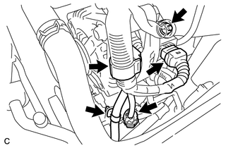
(d) Disconnect the connector from the compressor and magnetic clutch.
(e) Disconnect the 2 wire harness clamps.
|
(f) Remove the 2 bolts. |
|
|
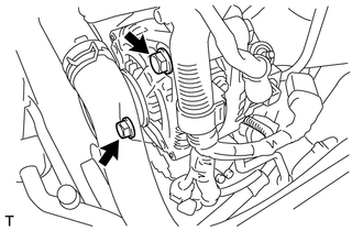
(g) Remove the bolt and generator assembly. |
|
(h) Disconnect the wire harness clamp and remove the bolt and generator bracket.
|
(i) Remove the bolt and wire harness clamp. |
|
 Components
COMPONENTS
ILLUSTRATION
ILLUSTRATION
ILLUSTRATION
...
 Disassembly
DISASSEMBLY
PROCEDURE
1. REMOVE GENERATOR REAR END COVER
(a) Remove the 3 nuts and generator rear end cover.
2. REMOVE TERMINAL INSULATOR
...
Other materials about Toyota Venza:
Removal
REMOVAL
PROCEDURE
1. DISCONNECT CABLE FROM NEGATIVE BATTERY TERMINAL
NOTICE:
When disconnecting the cable, some systems need to be initialized after the cable
is reconnected (See page ).
2. REMOVE RADIATOR RESERVE TANK ASSEMBLY
(a) Remove t ...
Installation
INSTALLATION
PROCEDURE
1. INSTALL WATER PUMP ASSEMBLY
(a) Install a new gasket and the water pump with the 7 bolts.
Torque:
21 N·m {214 kgf·cm, 15 ft·lbf}
2. INSTALL V-RIBBED BELT TENSIONE ...
Coolant Thermostat (Coolant Temperature Below Thermostat Regulating Temperature)
(P0128)
DESCRIPTION
HINT:
This DTC relates to the thermostat.
This DTC is stored when the engine coolant temperature does not reach 75°C (167°F)
despite sufficient engine warm-up time having elapsed.
DTC No.
DTC Detection Condition
...

0.1312