Toyota Venza: Vehicle Speed Signal Error (Test Mode DTC) (C2191/91)
DESCRIPTION
The tire pressure warning ECU receives a vehicle speed signal from the combination meter. This DTC is stored upon entering signal check mode (test mode), and cleared when a vehicle speed signal of 20 km/h (12 mph) is detected for 3 seconds or more. This DTC is output only in signal check mode.
|
DTC No. |
DTC Detection Condition |
Trouble Area |
|---|---|---|
|
C2191/91 |
Test mode procedure is performed |
|
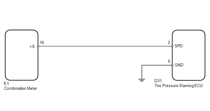
WIRING DIAGRAM
CAUTION / NOTICE / HINT
NOTICE:
- When replacing the tire pressure warning ECU, read the transmitter IDs stored in the old ECU using the Techstream and write them down before removal.
- It is necessary to perform registration (See page
.gif) ) of the transmitter IDs into the tire
) of the transmitter IDs into the tire
pressure warning ECU if the ECU has been replaced.
PROCEDURE
|
1. |
READ VALUE USING TECHSTREAM (VEHICLE SPEED) |
(a) Turn the ignition switch off.
(b) Connect the Techstream to the DLC3.
(c) Turn the ignition switch to ON.
(d) Turn the Techstream on.
(e) Enter the following menus: Chassis / Tire Pressure Monitor / Data List.
(f) Check that the values indicated on the Techstream and on the combination meter are the same.
Tire Pressure Monitor|
Tester Display |
Measurement Item/Range |
Normal Condition |
Diagnostic Note |
|---|---|---|---|
|
Vehicle Speed |
Vehicle speed/ min.: 0 km/h (0 mph) max.: 255 km/h (158 mph) |
Almost same as actual vehicle speed |
Speed indicated on combination meter |
OK:
Vehicle speed indicated on the Techstream and on the combination meter are the same.
| OK | .gif) |
USE SIMULATION METHOD TO CHECK |
|
.gif)
|
2. |
INSPECT TIRE PRESSURE WARNING ECU (SPD SIGNAL) |
|
(a) Disconnect the D31 ECU connector. |
|
(b) Jack up the vehicle.
(c) Move the shift lever to N.
(d) Turn the ignition switch to ON.
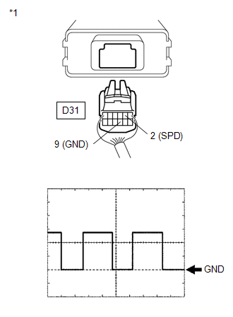
(e) Check the waveform of the ECU connector using an oscilloscope while turning the wheel slowly.
OK:
|
Tester Connection |
Switch Condition |
Specified Condition |
|---|---|---|
|
D31-2 (SPD) - D31-9 (GND) |
Ignition switch ON |
Correct waveform appears as shown |
|
*1 |
Rear view of wire harness connector (to Tire Pressure Warning ECU) |
|
Item |
Contents |
|---|---|
|
Tool Setting |
5 V/DIV., 20 ms/DIV. |
|
Vehicle Condition |
Driving wheels rotating slowly |
HINT:
The wavelength becomes shorter as the vehicle speed increases.
| OK | |
REPLACE TIRE PRESSURE WARNING ECU |
|
|
3. |
CHECK HARNESS AND CONNECTOR (ECU - COMBINATION METER) |
|
(a) Disconnect the D31 ECU connector. |
|
(b) Disconnect the E1 meter connector.
(c) Measure the resistance according to the value(s) in the table below.
Standard Resistance:
|
Tester Connection |
Condition |
Specified Condition |
|---|---|---|
|
D31-2 (SPD) - E1-16 (+S) |
Always |
Below 1 Ω |
|
D31-2 (SPD) - Body ground |
Always |
10 kΩ or higher |
|
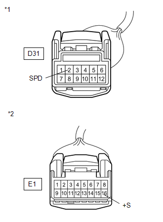
*1 |
Front view of wire harness connector (to Tire Pressure Warning ECU) |
|
*2 |
Front view of wire harness connector (to Combination Meter) |
| OK | |
REPLACE COMBINATION METER |
| NG | |
REPAIR OR REPLACE HARNESS OR CONNECTOR |
 Transmitter ID1 Error (C2141/41-C2144/44)
DESCRIPTION
The tire pressure warning valve and transmitter installed in each tire and wheel
assembly measures the tire pressures. The measured values are transmitted as radio
waves to the tire p ...
 Transmitter ID1 Operation Stop (C2111/11-C2114/14)
DESCRIPTION
The tire pressure warning valve and transmitter installed in each tire and wheel
assembly measures the tire pressures. The measured values are transmitted as radio
waves to the tire p ...
Other materials about Toyota Venza:
Speed Sensor(when Not Using The Engine Support Bridge)
Components
COMPONENTS
ILLUSTRATION
Removal
REMOVAL
PROCEDURE
1. REMOVE AUTOMATIC TRANSAXLE ASSEMBLY
HINT:
See the steps from "Remove Engine Assembly with transaxle" through "Remove Automatic
Transaxle Assembly" (See page ). ...
Terminals Of Ecm
TERMINALS OF ECM
HINT:
The standard voltage between each pair of ECM terminals is shown in the table
below. The appropriate conditions for checking each pair of terminals are also indicated.
The result of checks should be compared with the standard vol ...
Illumination Circuit
DESCRIPTION
Power is supplied to the radio and display receiver assembly and steering pad
switch assembly illumination when the light control switch is in the tail or head
position.
WIRING DIAGRAM
CAUTION / NOTICE / HINT
NOTICE:
The vehicle ...

0.1349