Toyota Venza: Components
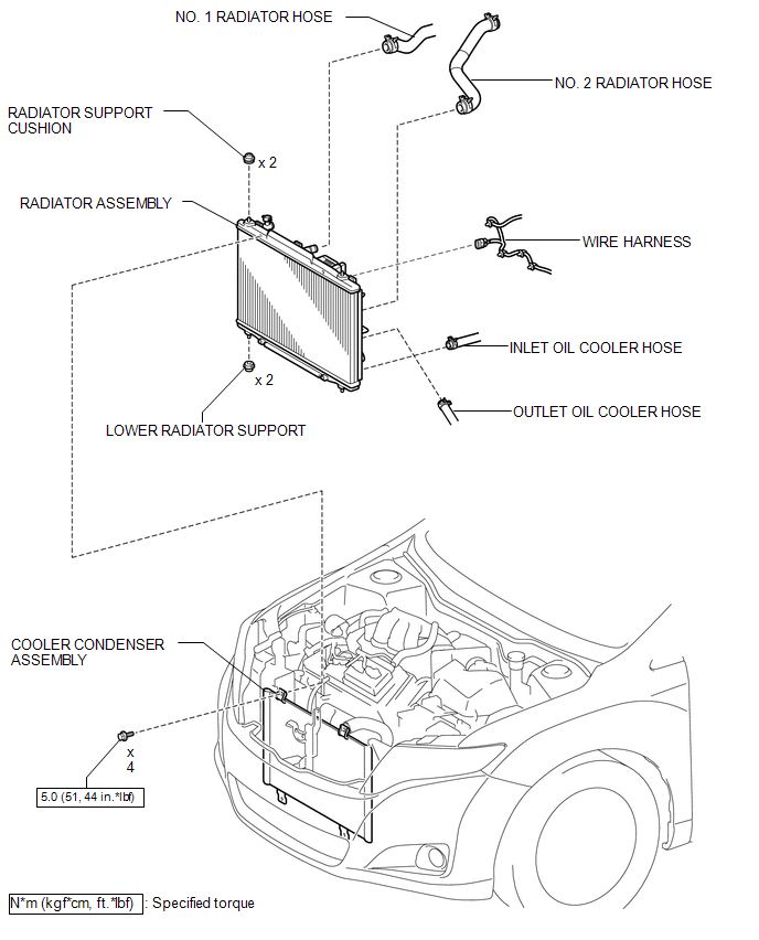
COMPONENTS
ILLUSTRATION
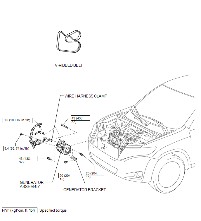
ILLUSTRATION
ILLUSTRATION
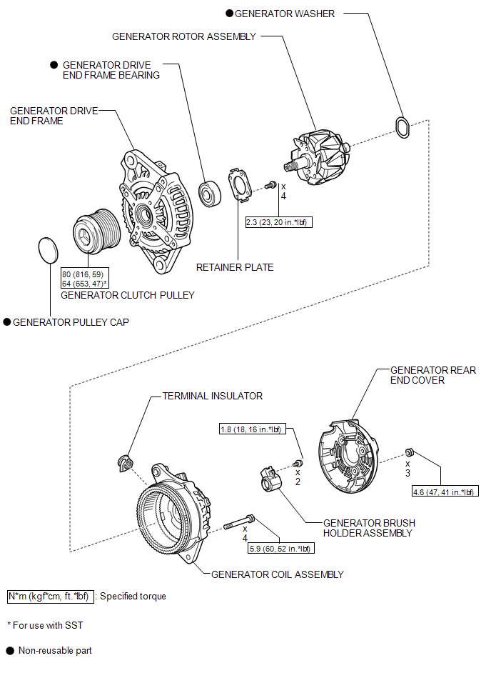
 Generator
...
 Removal
REMOVAL
PROCEDURE
1. DISCONNECT CABLE FROM NEGATIVE BATTERY TERMINAL
NOTICE:
When disconnecting the cable, some systems need to be initialized after the cable
is reconnected (See page ).
2. RE ...
Other materials about Toyota Venza:
Installation
INSTALLATION
CAUTION / NOTICE / HINT
HINT:
Use the same procedure for the RH side and LH side.
The procedure listed below is for the LH side.
PROCEDURE
1. INSTALL POWER WINDOW REGULATOR SWITCH ASSEMBLY
(a) Engage the 2 claws ...
Inspection
INSPECTION
PROCEDURE
1. INSPECT COMPRESSOR AND MAGNETIC CLUTCH (A/C LOCK SENSOR)
(a) Measure the resistance according to the value(s) in the table below.
Standard Resistance:
Tester Connection
Condition
...
Relay
On-vehicle Inspection
ON-VEHICLE INSPECTION
PROCEDURE
1. INSPECT DOME CUT RELAY
(a) Measure the resistance according to the value(s) in the table below.
Standard Resistance:
Tester Connection
Condition
...

0.1474