Toyota Venza: Installation
INSTALLATION
PROCEDURE
1. TEMPORARILY INSTALL REAR STABILIZER BAR BRACKET LH (for Front Side)
|
(a) Temporarily install the rear stabilizer bar bracket LH (front side) with the bolt. HINT: Loosely tighten the bolt so that the bracket can be moved by hand. |
|
.png)
2. TEMPORARILY INSTALL REAR STABILIZER BAR BRACKET RH (for Front Side)
|
(a) Temporarily install the rear stabilizer bar bracket RH (front side) with the 2 bolts. HINT: Loosely tighten the bolts so that the bracket can be moved by hand. |
|
.png)
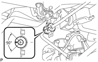
3. INSTALL REAR STABILIZER BUSHING (for LH Side)
|
(a) Install the rear stabilizer bushing (LH side) to the rear stabilizer bar. NOTICE: Make sure that the cutout of the rear stabilizer bushing is positioned within the range shown in the illustration. |
|
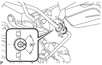
4. INSTALL REAR STABILIZER BUSHING (for RH Side)
|
(a) Install the rear stabilizer bushing (RH side) to the rear stabilizer bar. NOTICE: Make sure that the cutout of the rear stabilizer bushing is positioned within the range shown in the illustration. |
|
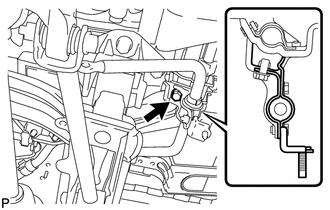
5. INSTALL REAR STABILIZER BAR BRACKET LH (for Rear Side)
|
(a) Install the rear stabilizer bar bracket LH (rear side) with the 2 bolts. Torque: 19 N·m {194 kgf·cm, 14 ft·lbf} |
|
.png)
6. INSTALL REAR STABILIZER BAR BRACKET RH (for Rear Side)
|
(a) Install the rear stabilizer bar bracket RH (rear side) with the 2 bolts. Torque: 19 N·m {194 kgf·cm, 14 ft·lbf} |
|
.png)
7. FULLY TIGHTEN REAR STABILIZER BAR BRACKET LH (for Front Side)
|
(a) Fully tighten the bolt. Torque: 54 N·m {551 kgf·cm, 40 ft·lbf} |
|
8. FULLY TIGHTEN REAR STABILIZER BAR BRACKET RH (for Front Side)
|
(a) Fully tighten the 2 bolts. Torque: 19 N·m {194 kgf·cm, 14 ft·lbf} |
|
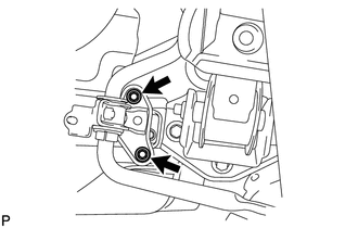
9. INSTALL REAR LOWER SUSPENSION BRACE (for LH Side)
|
(a) Install the rear lower suspension brace with the bolt and the nut. Torque: 35 N·m {357 kgf·cm, 26 ft·lbf} |
|
.png)
10. INSTALL REAR LOWER SUSPENSION BRACE (for RH Side)
HINT:
Perform the same procedure as the LH side.
11. INSTALL NO. 1 FLOOR UNDER COVER
.gif)
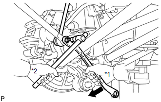
12. INSTALL REAR STABILIZER LINK ASSEMBLY LH
|
(a) Install the rear stabilizer link assembly LH to the rear shock absorber with coil spring LH with the nut. Text in Illustration
Torque: 39 N·m {400 kgf·cm, 29 ft·lbf} HINT: If the ball joint turns together with the nut, use a hexagon wrench (5 mm) to hold the stud bolt. |
|
.png)
|
(b) Install the rear stabilizer link assembly LH to the rear stabilizer bar with the nut. Text in Illustration
Torque: 39 N·m {400 kgf·cm, 29 ft·lbf} HINT: If the ball joint turns together with the nut, use a hexagon wrench (5 mm) to hold the stud bolt. |
|
13. INSTALL REAR STABILIZER LINK ASSEMBLY RH
HINT:
Perform the same procedure as the LH side.
14. INSTALL REAR WHEELS
Torque:
103 N·m {1050 kgf·cm, 76 ft·lbf}
 Removal
REMOVAL
PROCEDURE
1. REMOVE REAR WHEELS
2. REMOVE REAR STABILIZER LINK ASSEMBLY LH
(a) Remove the nut and separate the rear stabilizer link assembly LH
from the rear stabilizer bar. ...
 Rear Strut Rod
...
Other materials about Toyota Venza:
Power Management Control ECU Communication Stop Mode
DESCRIPTION
Detection Item
Symptom
Trouble Area
Power Management Control ECU Communication Stop Mode
"Electric Power Control" is not displayed on the CAN Bus Check
screen ...
Sound Signal Circuit between Navigation Receiver Assembly and Stereo Component
Amplifier
DESCRIPTION
The navigation receiver assembly sends a sound signal to the stereo component
amplifier assembly via this circuit.
The sound signal that has been sent is amplified by the stereo component amplifier
assembly, and then is sent to the speakers.
...
Door Control Switch
Components
COMPONENTS
ILLUSTRATION
Inspection
INSPECTION
PROCEDURE
1. INSPECT DOOR CONTROL SWITCH ASSEMBLY
(a) Measure the resistance according to the value(s) in the table below.
Standard Resistance:
Tester Conn ...

0.1291