Toyota Venza: Removal
REMOVAL
PROCEDURE
1. DISCONNECT CABLE FROM NEGATIVE BATTERY TERMINAL
NOTICE:
When disconnecting the cable, some systems need to be initialized after the cable
is reconnected (See page .gif) ).
).
2. REMOVE UPPER CONSOLE PANEL SUB-ASSEMBLY (w/o Seat Heater System)
3. REMOVE UPPER CONSOLE PANEL SUB-ASSEMBLY (w/ Seat Heater System)
4. REMOVE NO. 2 CONSOLE BOX CARPET
5. REMOVE CONSOLE BOX ASSEMBLY
6. REMOVE AIR CONDITIONING CONTROL ASSEMBLY
7. REMOVE FRONT DOOR SCUFF PLATE LH
8. REMOVE COWL SIDE TRIM SUB-ASSEMBLY LH
9. REMOVE LOWER NO. 1 INSTRUMENT PANEL FINISH PANEL
10. REMOVE FRONT DOOR SCUFF PLATE RH
11. REMOVE COWL SIDE TRIM SUB-ASSEMBLY RH
12. REMOVE NO. 2 INSTRUMENT PANEL UNDER COVER SUB-ASSEMBLY
13. REMOVE LOWER INSTRUMENT PANEL SUB-ASSEMBLY
14. REMOVE SHIFT LEVER KNOB SUB-ASSEMBLY
15. REMOVE CONSOLE BOX SUB-ASSEMBLY
16. REMOVE LOWER STEERING COLUMN COVER
17. REMOVE UPPER STEERING COLUMN COVER
18. REMOVE INSTRUMENT CLUSTER FINISH PANEL
19. REMOVE LOWER INSTRUMENT PANEL FINISH PANEL ASSEMBLY
|
(a) Disengage the 4 claws. |
|
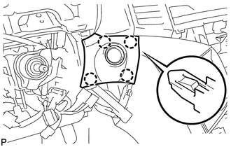
(b) Disconnect the connector and remove the lower instrument panel finish panel assembly.
20. REMOVE ENGINE SWITCH
|
(a) Detach the 2 claws and remove the engine switch. |
|
 Inspection
INSPECTION
PROCEDURE
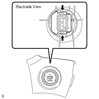
1. INSPECT ENGINE SWITCH
(a) Measure the resistance according to the value(s) in the table below.
Standard Resistance:
Tester Connection
Switch Condi ...
 Installation
INSTALLATION
PROCEDURE
1. INSTALL ENGINE SWITCH
(a) Attach the 2 claws to install the engine switch.
2. INSTALL LOWER INSTRUMENT PANEL FI ...
Other materials about Toyota Venza:
Precaution
PRECAUTION
NOTICE:
When disconnecting the cable from the negative (-) battery terminal, initialize
the following systems after the cable is reconnected.
System Name
See Procedure
Back Door Closer System
...
Dtc Check / Clear
DTC CHECK / CLEAR
1. CHECK DTCS
(a) Turn the engine switch off.
(b) Connect the Techstream to the DLC3.
(c) Turn the engine switch on (IG).
(d) Turn the Techstream on.
(e) Check for DTCs. Enter the following menus: Body Electrical / Smart Key /
Trouble ...
Pressure Control Solenoid "G" Performance (Shift Solenoid Valve SL4) (P2808)
DESCRIPTION
The TCM uses the vehicle speed signal and signals from the transmission speed
sensors (NC, NT) to detect the actual gear (1st, 2nd, 3rd, 4th, 5th or 6th gear).
Then the TCM compares the actual gear with the shift schedule in the TCM memory
to ...

0.1126