Toyota Venza: Components
COMPONENTS
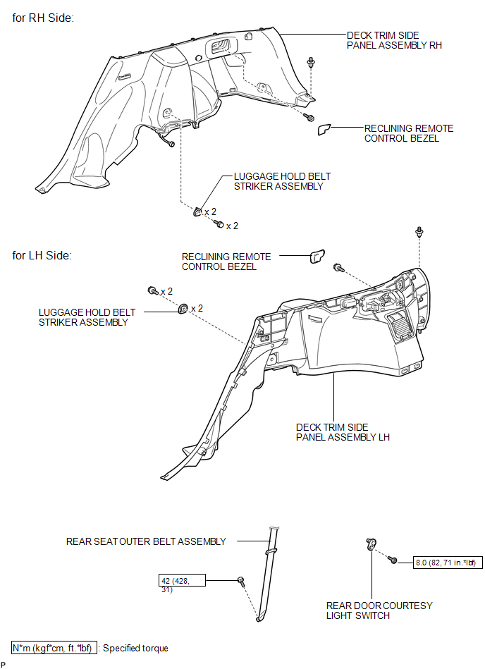
ILLUSTRATION
.png)
ILLUSTRATION
.png)
ILLUSTRATION
.png)
ILLUSTRATION
.png)
ILLUSTRATION

 Removal
REMOVAL
PROCEDURE
1. REMOVE REAR DOOR SCUFF PLATE
2. DISCONNECT REAR DOOR OPENING TRIM WEATHERSTRIP
3. REMOVE TONNEAU COVER ASSEMBLY (w/ Tonneau Cover)
4. REMOVE DECK BOARD ASSEMBLY
...
Other materials about Toyota Venza:
Terminals Of Ecu
TERMINALS OF ECU
1. OCCUPANT CLASSIFICATION ECU (for Power Seat)
Terminal No. (Symbol)
Wiring Color
Terminal Description
Condition
Specification
S12-1 (+B) - S12-3 (GND)
GR ...
Occupant Classification Ecu
Components
COMPONENTS
ILLUSTRATION
ILLUSTRATION
On-vehicle Inspection
ON-VEHICLE INSPECTION
CAUTION / NOTICE / HINT
CAUTION:
Be sure to follow the correct removal and installation procedures of the occupant
classification ECU.
PROCEDURE
1. ...
Removal
REMOVAL
PROCEDURE
1. DISCONNECT CABLE FROM NEGATIVE BATTERY TERMINAL
NOTICE:
When disconnecting the cable, some systems need to be initialized after the cable
is reconnected (See page ).
2. REMOVE RADIATOR ASSEMBLY
HINT:
See page
3. REMOVE V-RIBBE ...

0.1688