Toyota Venza: Check For Intermittent Problems
CHECK FOR INTERMITTENT PROBLEMS
1. CHECK FOR INTERMITTENT PROBLEMS
HINT:
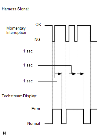
A momentary interruption (open circuit) in the connectors and/or wire harness between the sensors and ECUs can be detected using the ECU Data List function of the Techstream.
(a) Turn the ignition switch off.
(b) Connect the Techstream to the DLC3.
(c) Turn the ignition switch to ON.
(d) Turn the Techstream on.
(e) Follow the directions on the Techstream to display the Data List and select areas where momentary interruption should be monitored.
HINT:
- A momentary interruption (open circuit) cannot be detected for 3 seconds after the ignition switch is turned to ON (initial check).
- If the status remains on (Error displayed), check the continuity between the ECU and the sensors, or between ECUs.
- The Error display on the Techstream remains on for 1 second after the harness signal changes from momentary interruption (open circuit) to normal.
|
Tester Display |
Measurement Item/Range |
Normal Condition |
Diagnostic Note |
|---|---|---|---|
|
EFI Communication Open |
EFI communication open detection / Error or Normal |
Error: Momentary interruption Normal: Normal |
- |
|
Yaw Rate Open |
Yaw rate sensor open detection / Error or Normal |
Error: Momentary interruption Normal: Normal |
- |
|
Deceleration Open |
Acceleration sensor open detection / Error or Normal |
Error: Momentary interruption Normal: Normal |
- |
|
Steering Open |
Steering angle sensor open detection / Error or Normal |
Error: Momentary interruption Normal: Normal |
- |
|
IG Voltage Value Decreased |
IG voltage value decrease detection / Error or Normal |
Error: Decrease Normal: Normal |
- |
|
FR Speed Sensor Voltage Open |
Front speed sensor RH voltage open detection / Error or Normal |
Error: Momentary interruption Normal: Normal |
- |
|
FL Speed Sensor Voltage Open |
Front speed sensor LH voltage open detection / Error or Normal |
Error: Momentary interruption Normal: Normal |
- |
|
RR Speed Sensor Voltage Open |
Rear speed sensor RH voltage open detection / Error or Normal |
Error: Momentary interruption Normal: Normal |
- |
|
RL Speed Sensor Voltage Open |
Rear speed sensor LH voltage open detection / Error or Normal |
Error: Momentary interruption Normal: Normal |
- |
(f) While observing the screen, gently jiggle the connector or wire harness between the ECU and sensors, or between ECUs.
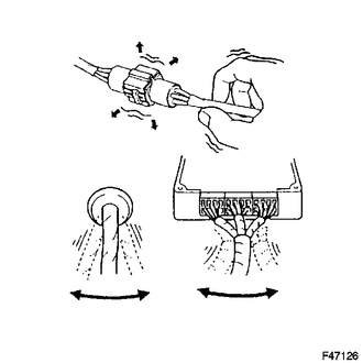
OK:
Normal display appears.
HINT:
The connector and/or wire harness has a momentary interruption (open circuit) if the display changes. Repair or replace the connector and/or wire harness as one of them is faulty.
 Calibration
CALIBRATION
1. DESCRIPTION
(a) Follow the chart below to perform calibration.
Parts to be Replaced
Necessary Operation
Brake actuator assembly (Skid control E ...
 Test Mode Procedure
TEST MODE PROCEDURE
1. WARNING LIGHT AND INDICATOR LIGHT INITIAL CHECK
(a) Release the parking brake.
NOTICE:
Before releasing the parking brake, move the shift lever to P for safety.
HINT:
When ...
Other materials about Toyota Venza:
Installation
INSTALLATION
PROCEDURE
1. INSTALL FRONT DOOR OUTSIDE HANDLE ASSEMBLY
(a) Insert the front end of the front door outside handle assembly into
the front door outside handle frame.
(b) Insert the r ...
Removal
REMOVAL
PROCEDURE
1. REMOVE REAR SEAT HEADREST ASSEMBLY
(a) Press the headrest support button and pull up the rear seat headrest
assembly as shown in the illustration.
2. REMOVE REAR SEAT CENTER ...
Components
COMPONENTS
ILLUSTRATION
ILLUSTRATION
ILLUSTRATION
ILLUSTRATION
ILLUSTRATION
...

0.1552