Toyota Venza: Inspection
INSPECTION
PROCEDURE
1. INSPECT ENGINE SWITCH
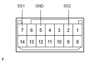
(a) Measure the resistance according to the value(s) in the table below.
Standard Resistance:
|
Tester Connection |
Switch Condition |
Specified Condition |
|---|---|---|
|
7 (SS1) - 5 (GND) |
Not pushed |
10 kΩ or higher |
|
2 (SS2) - 5 (GND) |
Not pushed |
10 kΩ or higher |
|
7 (SS1) - 5 (GND) |
Pushed |
15 Ω |
|
2 (SS2) - 5 (GND) |
Pushed |
15 Ω |
If the result is not as specified, replace the engine switch.
(b) Apply battery voltage between the terminals of the switch, and check the illumination condition of the engine switch.
HINT:
- If a positive (+) battery lead and a negative (-) battery lead are incorrectly connected, the engine switch indicator light will not illuminate.
- If the voltage is too low, the indicator light will not illuminate.
OK:
|
Measurement Condition |
Specified Condition |
|---|---|
|
Battery positive (+) → Terminal 11 (SWIL) Battery negative (-) → Terminal 4 (COM) or 5 (GND) |
Illuminates |
|
Battery positive (+) → Terminal 12 (INDS) Battery negative (-) → Terminal 4 (COM) or 5 (GND) |
Illuminates |
|
Battery positive (+) → Terminal 13 (INDW) Battery negative (-) → Terminal 4 (COM) or 5 (GND) |
Illuminates |
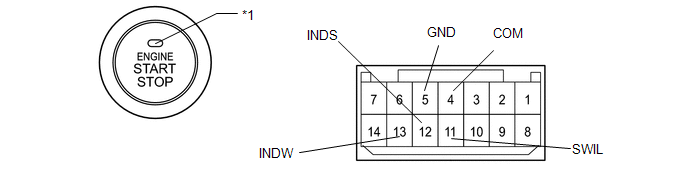 Text in Illustration
|
*1 |
Indicator Light |
If the result is not as specified, replace the engine switch.
 Components
COMPONENTS
ILLUSTRATION
ILLUSTRATION
...
 Removal
REMOVAL
PROCEDURE
1. DISCONNECT CABLE FROM NEGATIVE BATTERY TERMINAL
NOTICE:
When disconnecting the cable, some systems need to be initialized after the cable
is reconnected (See page ).
2. RE ...
Other materials about Toyota Venza:
Speed Sensor Rotor Faulty (C1237/37,C1275/75-C1278/78)
DESCRIPTION
The skid control ECU measures the speed of each wheel by receiving signals from
the speed sensor.
These signals are used for recognizing that all four wheels are operating properly.
Therefore, all wheel signals must be equal.
DTCs C1275/75 to ...
Check CAN Bus Line for Short to GND
DESCRIPTION
There may be a short circuit between the CAN bus main wire and GND when there
is no resistance between terminals 6 (CANH) and 4 (CG) or 14 (CANL) and 4 (CG) of
the DLC3.
Symptom
Trouble Area
No resistanc ...
Removal
REMOVAL
PROCEDURE
1. PRECAUTION
CAUTION:
Be sure to read Precaution thoroughly before servicing (See page
).
2. TURN FRONT WHEELS TO FACE STRAIGHT AHEAD
3. DISCONNECT CABLE FROM NEGATIVE BATTERY TERMINAL
CAUTION:
Wait at least 90 seconds after discon ...

0.1507