Toyota Venza: Removal
REMOVAL
PROCEDURE
1. DISCHARGE FUEL SYSTEM PRESSURE
HINT:
(See page .gif) ).
).
2. DISCONNECT CABLE FROM NEGATIVE BATTERY TERMINAL
NOTICE:
When disconnecting the cable, some systems need to be initialized after the cable
is reconnected (See page ).
3. REMOVE FUEL SUCTION TUBE ASSEMBLY WITH PUMP AND GAUGE
(a) Remove the fuel suction tube assembly with pump and gauge (See page
).
4. REMOVE REAR NO. 2 FLOOR SERVICE HOLE COVER
5. REMOVE FUEL SENDER GAUGE ASSEMBLY
6. DRAIN FUEL
7. REMOVE CENTER EXHAUST PIPE ASSEMBLY
HINT:
(See page ).
8. REMOVE PROPELLER WITH CENTER BEARING SHAFT ASSEMBLY (for AWD)
(a) Remove the propeller with center bearing shaft assembly (See page
).
9. REMOVE ELECTRO MAGNETIC CONTROL COUPLING SUB-ASSEMBLY (for AWD)
10. REMOVE FRONT FLOOR BRACE LH
|
(a) Remove the bolt, 2 nuts and front floor brace LH. |
|
11. REMOVE FRONT FLOOR BRACE RH
(a) Remove the bolt, 2 nuts and front floor brace RH.
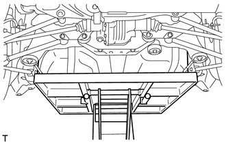
12. REMOVE NO. 1 FUEL TANK PROTECTOR SUB-ASSEMBLY
|
(a) Remove the 4 bolts and fuel tank protector sub-assembly. |
|
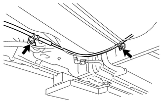
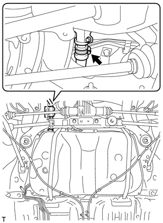
13. SEPARATE NO. 2 PARKING BRAKE CABLE ASSEMBLY
|
(a) Remove the set bolt and set nut of the No. 2 parking brake cable assembly. |
|
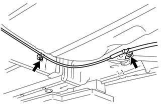
14. SEPARATE NO. 3 PARKING BRAKE CABLE ASSEMBLY
|
(a) Remove the set bolt and set nut of the No. 3 parking brake cable assembly. |
|
15. REMOVE FUEL TANK ASSEMBLY
|
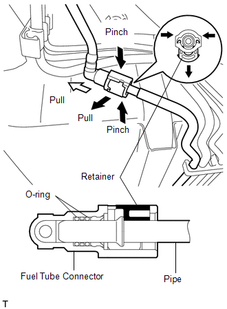
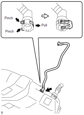
(a) Disconnect the fuel pump tube. (1) Pinch the tabs of the retainer to release the lock claws and pull it down as shown in the illustration. (2) Pull out the fuel tank main tube. NOTICE:
|
|
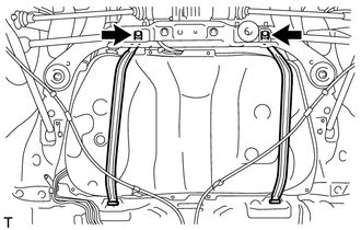
(b) Disconnect the fuel tank vent hose sub-assembly from the charcoal canister assembly.
.png) Text in Illustration
Text in Illustration
|
*1 |
Tube Connector |
*2 |
O-ring |
|
*3 |
Retainer |
*4 |
Pipe (Charcoal Canister Assembly) |
.png) |
Pinch |
.png) |
Pull |
NOTICE:
- Remove any dirt or foreign matter on the tube connector before performing this work.
- Do not allow any scratches or foreign matter to get on the parts when disconnecting them as the tube connector has an O-ring that seals the pipe.
- Perform this work by hand. Do not use any tools.
- Do not forcibly bend, twist or turn the fuel tank vent hose sub-assembly.
- Protect the disconnected parts by covering them with plastic bags after disconnecting the fuel tank vent hose sub-assembly.
- If the tube connector and pipe are stuck, push and pull on them to release.
HINT:
Do not remove the retainer.
|
(c) Disengage the 2 clamps and separate the fuel tank vent hose sub-assembly. |
|
|
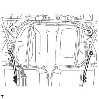
(d) Set up an engine lifter underneath the fuel tank. |
|
|
(e) Remove the 2 set bolts of the fuel tank bands. |
|
|
(f) Remove the hose clamp and disconnect the fuel tank to filter pipe hose. |
|
(g) Remove the fuel tank.
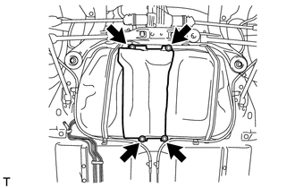
|
(h) Remove the 2 pins and 2 fuel tank bands as shown in the illustration. |
|
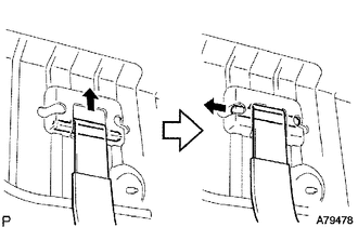
|
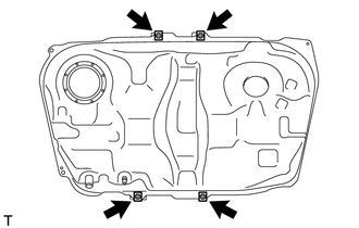
(i) Remove the 4 clip nuts. |
|
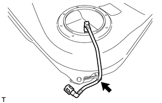
16. REMOVE FUEL TANK VENT HOSE SUB-ASSEMBLY
|
(a) Remove the fuel tank vent hose sub-assembly from the fuel tank. |
|
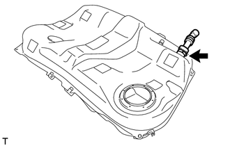
17. REMOVE FUEL TANK TO FILLER PIPE HOSE
|
(a) Loosen the hose clamp bolt and remove the fuel tank to filler pipe hose from the fuel tank assembly. |
|
18. REMOVE FUEL TANK MAIN TUBE SUB-ASSEMBLY
|
(a) Remove the fuel tank main tube from the fuel main tube support. |
|
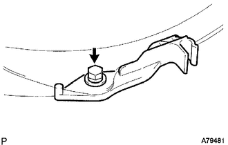
19. REMOVE FUEL MAIN TUBE SUPPORT
|
(a) Remove the bolt and the fuel main tube support. |
|
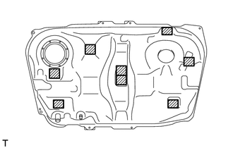
20. REMOVE NO. 1 FUEL TANK CUSHION
|
(a) Remove the 8 No. 1 fuel tank cushions. |
|
 Components
COMPONENTS
ILLUSTRATION
ILLUSTRATION
ILLUSTRATION
ILLUSTRATION
...
 Installation
INSTALLATION
PROCEDURE
1. INSTALL NO. 1 FUEL TANK CUSHION
(a) Install 8 new No. 1 fuel tank cushions to the fuel tank.
2. INSTALL FUEL MAI ...
Other materials about Toyota Venza:
Air Conditioning Pressure Sensor
Components
COMPONENTS
ILLUSTRATION
Installation
INSTALLATION
PROCEDURE
1. INSTALL AIR CONDITIONING PRESSURE SENSOR
(a) Sufficiently apply compressor oil to a new air conditioning pressure
sensor.
Compressor oil:
ND-OIL 8 or e ...
Diagnostic Trouble Code Chart
DIAGNOSTIC TROUBLE CODE CHART
HINT:
If a trouble code is displayed during the DTC check, inspect the trouble areas
listed for that code. For details of the code, refer to the "See page" below.
Power Steering System
DTC Code
...
Removal
REMOVAL
PROCEDURE
1. REMOVE REAR DOOR SCUFF PLATE RH
HINT:
Use the same procedure for the RH side and the LH side (See page
).
2. REMOVE REAR DOOR OPENING TRIM WEATHERSTRIP RH
HINT:
Use the same procedure for the RH side and the LH side (See page
). ...

0.1355