Toyota Venza: Installation
INSTALLATION
PROCEDURE
1. INSTALL NO. 1 FUEL TANK CUSHION
|
(a) Install 8 new No. 1 fuel tank cushions to the fuel tank. |
|
.png)
2. INSTALL FUEL MAIN TUBE SUPPORT
|
(a) Install the fuel main tube support with the bolt. Torque: 5.4 N·m {55 kgf·cm, 48 in·lbf} |
|
.png)
3. INSTALL FUEL TANK MAIN TUBE SUB-ASSEMBLY
|
(a) Install the fuel tank main tube to the fuel main tube support. |
|
.png)
4. INSTALL FUEL TANK TO FILLER PIPE HOSE
|
(a) Install the fuel tank to filler pipe hose to the fuel tank assembly with the clamp. |
|
5. INSTALL FUEL TANK VENT HOSE SUB-ASSEMBLY
|
(a) Install the fuel tank vent hose sub-assembly. |
|
6. INSTALL FUEL SENDER GAUGE ASSEMBLY
.gif)
7. INSTALL FUEL TANK ASSEMBLY
|
(a) Install the 4 clip nuts. |
|
.png)
|
(b) Install the 2 fuel tank bands with the 2 pins. |
|
(c) Set the fuel tank assembly onto the engine lifter.
|
(d) Lift up the engine lifter. NOTICE: Slowly raise the lifter so as to not drop the fuel tank assembly. |
|
.png)
|
(e) Install the fuel tank assembly with the fuel tank bands and 2 bolts. Torque: 45 N·m {459 kgf·cm, 33 ft·lbf} |
|
.png)
|
(f) Connect the fuel tank to filler pipe hose with the clamp. |
|
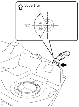
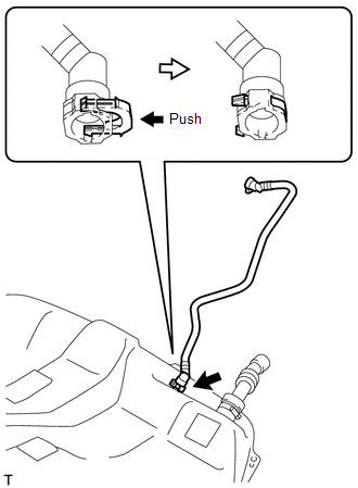
(g) Connect the 2 clamps and install the fuel tank vent hose sub-assembly.
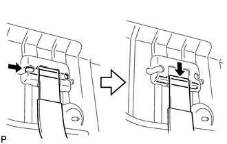
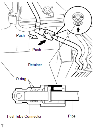
(h) Push in the tube connector to the pipe and push up the retainer to connect the fuel tank vent hose sub-assembly.
.png) Text in Illustration
Text in Illustration
|
*1 |
Retainer |
.png) |
Push Up |
NOTICE:
- Check that there are no scratches or foreign matter around the connected part of the tube connector and pipe before performing this work.
- After connecting the vent line tube, check that the fuel tank vent hose sub-assembly is securely connected by pulling on the tube connector and the charcoal canister.
|
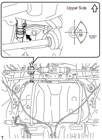
(i) Connect the fuel tank main tube sub-assembly. (1) Push in the fuel pump tube connector to the pipe and push up the retainer so that the claws engage. NOTICE:
|
|
8. INSTALL NO. 3 PARKING BRAKE CABLE ASSEMBLY
|
(a) Install the No. 3 parking brake cable assembly with the bolt and nut. Torque: 6.0 N·m {61 kgf·cm, 53 in·lbf} |
|
.png)
9. INSTALL NO. 2 PARKING BRAKE CABLE ASSEMBLY
|
(a) Install the No. 2 parking brake cable assembly with the bolt and nut. Torque: 6.0 N·m {61 kgf·cm, 53 in·lbf} |
|
.png)
10. INSTALL NO. 1 FUEL TANK PROTECTOR SUB-ASSEMBLY
|
(a) Install the No. 1 fuel tank protector sub-assembly with the 4 bolts. Torque: 5.4 N·m {55 kgf·cm, 48 in·lbf} |
|
.png)
11. INSTALL FRONT FLOOR BRACE LH
.png)
(a) Install the bolt, 2 nuts and front floor brace LH.
Torque:
56 N·m {571 kgf·cm, 41 ft·lbf}
12. INSTALL FRONT FLOOR BRACE RH
(a) Install the bolt, 2 nuts and front floor brace RH.
Torque:
56 N·m {571 kgf·cm, 41 ft·lbf}
13. INSTALL ELECTRO MAGNETIC CONTROL COUPLING SUB-ASSEMBLY (for AWD)
14. INSTALL PROPELLER WITH CENTER BEARING SHAFT ASSEMBLY (for AWD)
(a) Install the propeller with center bearing shaft assembly (See page
).
15. INSTALL CENTER EXHAUST PIPE ASSEMBLY
HINT:
(See page ).
16. ADD FUEL
17. INSTALL REAR NO. 2 FLOOR SERVICE HOLE COVER
18. INSTALL FUEL SUCTION TUBE ASSEMBLY WITH PUMP AND GAUGE
(a) Install the fuel suction tube assembly with pump and gauge (See page
).
19. CONNECT CABLE TO NEGATIVE BATTERY TERMINAL
NOTICE:
When disconnecting the cable, some systems need to be initialized after the cable
is reconnected (See page ).
20. INSPECT FOR EXHAUST GAS LEAK
 Removal
REMOVAL
PROCEDURE
1. DISCHARGE FUEL SYSTEM PRESSURE
HINT:
(See page ).
2. DISCONNECT CABLE FROM NEGATIVE BATTERY TERMINAL
NOTICE:
When disconnecting the cable, some systems need to be initiali ...

Other materials about Toyota Venza:
Heated Oxygen Sensor
Components
COMPONENTS
ILLUSTRATION
Removal
REMOVAL
PROCEDURE
1. REMOVE NO. 1 ENGINE UNDER COVER
2. REMOVE NO. 2 ENGINE UNDER COVER
3. REMOVE FRONT EXHAUST PIPE ASSEMBLY
4. REMOVE HEATED OXYGEN SENSOR
(a) Using SST, remove the heat ...
Removal
REMOVAL
PROCEDURE
1. DISCONNECT CABLE FROM NEGATIVE BATTERY TERMINAL
NOTICE:
When disconnecting the cable, some systems need to be initialized after the cable
is reconnected (See page ).
2. REMOVE COOL AIR INTAKE DUCT SEAL
3. REMOVE NO. 1 ENGINE CO ...
How To Proceed With Troubleshooting
CAUTION / NOTICE / HINT
HINT:
Use the following procedure to troubleshoot the cruise control system.
*: Use the Techstream.
PROCEDURE
1.
VEHICLE BROUGHT TO WORKSHOP
NEXT
...

0.1126