Toyota Venza: Components
COMPONENTS
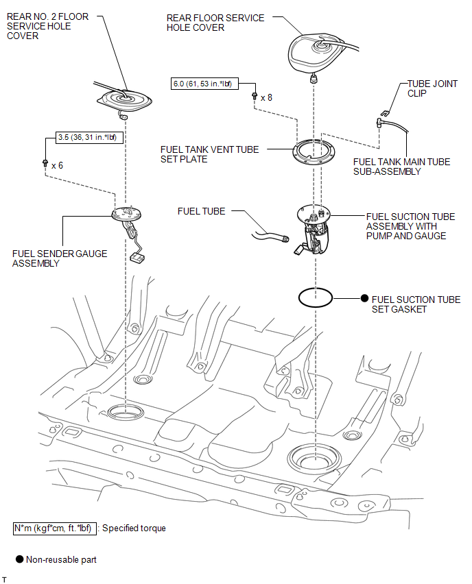
ILLUSTRATION
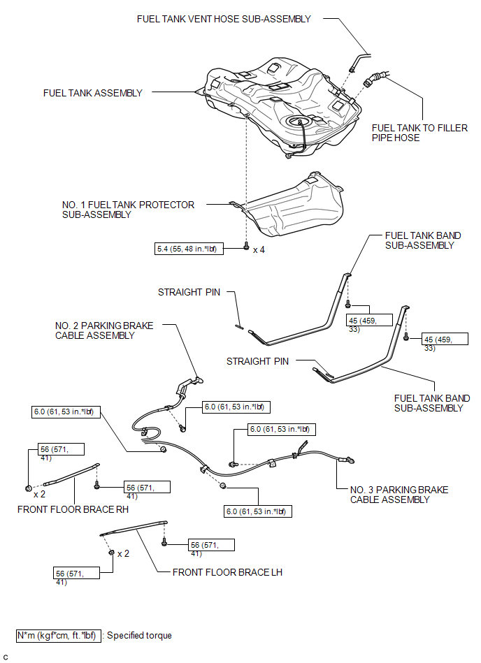
ILLUSTRATION
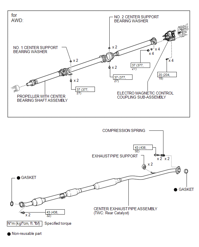
ILLUSTRATION
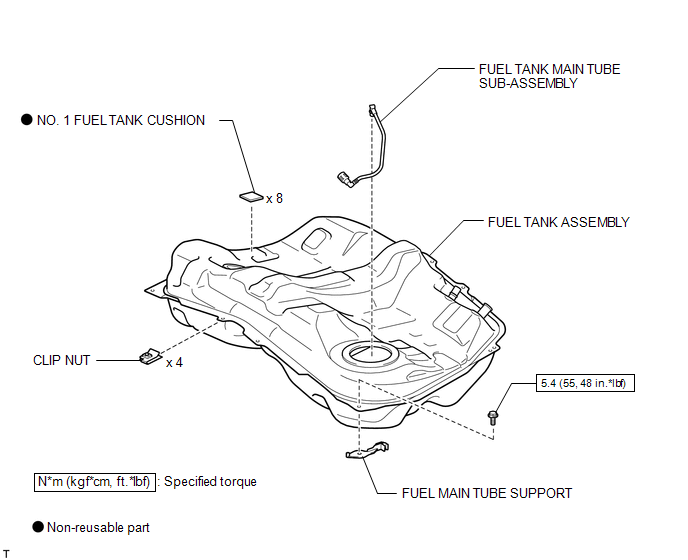
ILLUSTRATION
 Fuel Tank
...
 Removal
REMOVAL
PROCEDURE
1. DISCHARGE FUEL SYSTEM PRESSURE
HINT:
(See page ).
2. DISCONNECT CABLE FROM NEGATIVE BATTERY TERMINAL
NOTICE:
When disconnecting the cable, some systems need to be initiali ...
Other materials about Toyota Venza:
Replacement
REPLACEMENT
CAUTION / NOTICE / HINT
CAUTION:
Prolonged and repeated contact with engine oil will result in the removal
of natural oils from the skin, leading to dryness, irritation and dermatitis.
In addition, used engine oil contains potent ...
Precaution
PRECAUTION
1. PRECAUTION FOR DISCONNECTING THE BATTERY CABLE
NOTICE:
When disconnecting the cable from the negative (-) battery terminal, initialize
the following systems after the cable is reconnected:
System
See Procedure
...
Open or Short Circuit in ABS Solenoid Relay Circuit (C0278/11)
DESCRIPTION
The ABS solenoid relay supplies power to the ABS solenoid and TRAC solenoid.
The solenoid relay is turned on 1.5 seconds after the ignition switch is turned
to ON, and is turned off if an open or short in the solenoid is detected by self
diag ...

0.1772