
Toyota Venza: Radiator Grille
Components
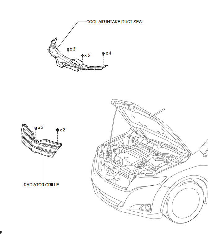
COMPONENTS
ILLUSTRATION
Removal
REMOVAL
PROCEDURE
1. REMOVE COOL AIR INTAKE DUCT SEAL
.gif)
2. REMOVE RADIATOR GRILLE
|
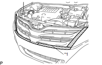
(a) Put protective tape around the radiator grille. Text in Illustration
|
|
|
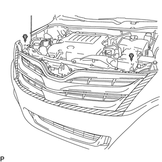
(b) Remove the 2 bolts. |
|
|
(c) Using a clip remover, remove the 3 clips. |
|
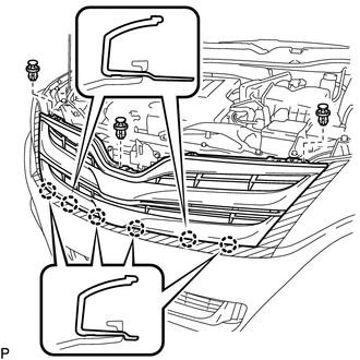
(d) Disengage the 6 claws and remove the radiator grille.
Installation
INSTALLATION
PROCEDURE
1. INSTALL RADIATOR GRILLE
(a) Engage the 6 claws.
(b) Install the 3 clips.
(c) Install the radiator grille with the 2 bolts.
2. INSTALL COOL AIR INTAKE DUCT SEAL
.gif)
 Installation
INSTALLATION
CAUTION / NOTICE / HINT
HINT:
When installing new name plates and emblem, heat the vehicle body, name plates
and emblem using a heat light.
Heating Temperature
Item
...
 Rear Bumper
...
Other materials about Toyota Venza:
Disassembly
DISASSEMBLY
PROCEDURE
1. REMOVE FRONT TRANSAXLE CASE OIL SEAL
(a) Using SST, remove the front transaxle case oil seal from the transaxle
housing.
SST: 09308-00010
2. REMOVE TRANSAXLE CASE OIL ...
Occupant Classification Sensor Power Supply Circuit Malfunction (B1793)
DESCRIPTION
The occupant classification sensor power supply circuit consists of the occupant
classification ECU and occupant classification sensors.
DTC B1793 is recorded when a malfunction is detected in the occupant classification
sensor power supply c ...
Terminals Of Ecu
TERMINALS OF ECU
1. CHECK AIR CONDITIONING AMPLIFIER ASSEMBLY
(a) Disconnect the D47 air conditioning amplifier assembly connector.
(b) Measure the voltage and resistance according to the value(s) in the table
below.
HINT:
Measure the values on the wi ...

0.1587