Toyota Venza: Reassembly
REASSEMBLY
PROCEDURE
1. INSTALL NO. 14 ROOF SILENCER PAD
(a) Align the markings on the roof headlining assembly with the No. 14 roof silencer pad and install the silencer pad using hot-melt glue as shown in the illustration.
.png)
2. INSTALL NO. 1 ROOF WIRE (w/o Sliding Roof)
(a) Install the No. 1 roof wire.
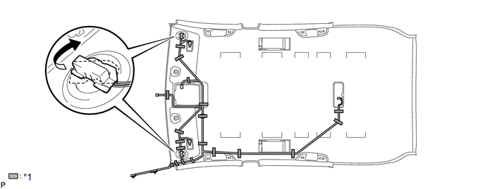 Text in Illustration
|
*1 |
Adhesive Tape |
- |
- |
(b) Turn the visor connectors clockwise approximately 90° to install the connectors to the roof headlining assembly.
(c) Apply adhesive tape to the locations shown in the illustration.
HINT:
As shown in the illustration, line up and secure the reference tape of the wire harness to the tip of the roof headlining assembly.
3. INSTALL NO. 1 ROOF WIRE (w/ Sliding Roof)
(a) Install the No. 1 roof wire.
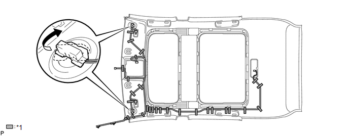 Text in Illustration
|
*1 |
Adhesive Tape |
- |
- |
(b) Turn the visor connectors clockwise approximately 90° to install the connectors to the roof headlining assembly.
(c) Apply adhesive tape to the locations shown in the illustration.
HINT:
As shown in the illustration, line up and secure the reference tape of the wire harness to the tip of the roof headlining assembly.
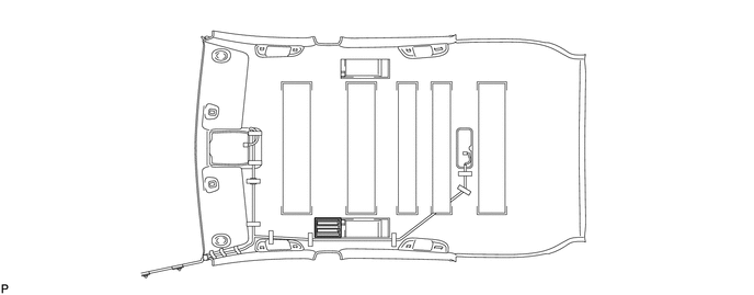
4. INSTALL NO. 2 ROOF SILENCER PAD (w/o Sliding Roof)
(a) Align the markings on the roof headlining assembly with the 2 No. 2 roof silencer pads and install the silencer pad using hot-melt glue or double-sided tape as shown in the illustration.
.png)
5. INSTALL NO. 3 ROOF SILENCER PAD (w/o Sliding Roof)
(a) Align the markings on the roof headlining assembly with the 3 No. 3 roof silencer pads and install the silencer pad using hot-melt glue or double-sided tape as shown in the illustration.
.png)
6. INSTALL FRONT SIDE RAIL SPACER LH (w/o Sliding Roof)
(a) Align the markings on the roof headlining assembly with the roof side rail spacer LH and install the spacer using hot-melt glue as shown in the illustration.
7. INSTALL FRONT SIDE RAIL SPACER RH (w/o Sliding Roof)
HINT:
Use the same procedure for the RH side and the LH side.
8. INSTALL VANITY LIGHT ASSEMBLY
(a) Install the vanity light assembly (See page
.gif) ).
).
HINT:
Use the same procedure for the RH side and the LH side.
9. INSTALL NO. 2 ANTENNA CORD SUB-ASSEMBLY (w/o Sliding Roof)
10. INSTALL NO. 2 ANTENNA CORD SUB-ASSEMBLY (w/ Sliding Roof)
 Removal
REMOVAL
PROCEDURE
1. REMOVE FRONT DOOR SCUFF PLATE LH
(a) Disengage the 3 clips, 7 claws and guide, and remove the front door
scuff plate LH.
...
 Installation
INSTALLATION
PROCEDURE
1. INSTALL ROOF HEADLINING ASSEMBLY (w/o Sliding Roof)
(a) Pull the roof headlining assembly into the vehicle through the back
door.
NOTICE:
Do not damag ...
Other materials about Toyota Venza:
System Diagram
SYSTEM DIAGRAM
Communication Table
Sender
Receiver
Signal
Line
ECM
Combination Meter ECU
CRUISE main indicator operation signal
SET indicator operation sig ...
Seat Heater System
Precaution
PRECAUTION
1. NOTICE FOR INITIALIZATION
HINT:
When disconnecting the cable from the negative (-) battery terminal, initialize
the following systems after the cable is reconnected.
System Name
See procedure
...
Diagnosis System
DIAGNOSIS SYSTEM
1. DESCRIPTION
(a) Lighting system data and the Diagnostic Trouble Codes (DTCs) can be read
from the Data Link Connector 3 (DLC3) of the vehicle. When the system seems to be
malfunctioning, use the Techstream to check for malfunctions an ...

0.1507