Toyota Venza: Removal
REMOVAL
PROCEDURE
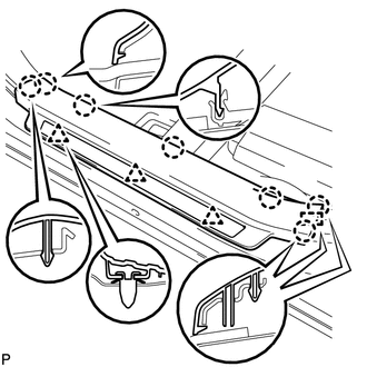
1. REMOVE FRONT DOOR SCUFF PLATE LH
|
(a) Disengage the 3 clips, 7 claws and guide, and remove the front door scuff plate LH. |
|
2. REMOVE COWL SIDE TRIM SUB-ASSEMBLY LH
|
(a) Remove the clip. |
|
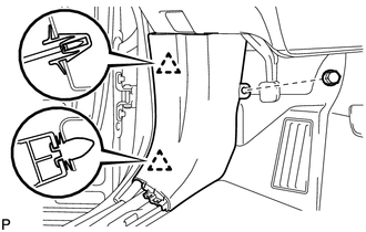
(b) Disengage the 2 clips and remove the cowl side trim sub-assembly LH.
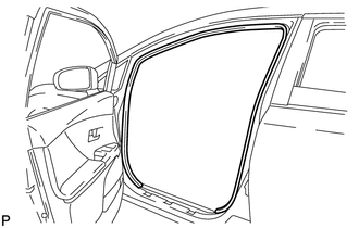
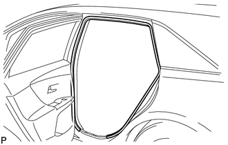
3. REMOVE FRONT DOOR OPENING TRIM WEATHERSTRIP LH
|
(a) Remove the front door opening trim weatherstrip LH. |
|
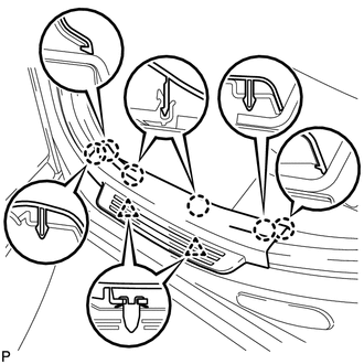
4. REMOVE FRONT PILLAR GARNISH LH
|
(a) Pull the upper part of the garnish toward the inside of the cabin and disengage the 2 clips. HINT: Make the front pillar garnish LH hang down from the front pillar garnish clip. |
|

(b) Turn the end of the front pillar garnish clip 90° with needle-nosed pliers and remove it from the front pillar garnish LH.
NOTICE:
- Front pillar garnish clips are reusable if they are not removed from the vehicle and have no damage.
- Replace the front pillar garnish clips with new ones if they are removed from the vehicle.
HINT:
Tape the needle-nosed pliers tip before use.
(c) Disengage the 3 guides and remove the front pillar garnish LH.
5. REMOVE REAR DOOR SCUFF PLATE LH
|
(a) Disengage the 2 clips and 6 claws, and remove the rear door scuff plate LH. |
|
6. REMOVE REAR DOOR OPENING TRIM WEATHERSTRIP LH
|
(a) Remove the rear door opening trim weatherstrip LH. |
|
7. REMOVE LAP BELT OUTER ANCHOR COVER (for LH Side)
.gif)
8. DISCONNECT FRONT SEAT OUTER BELT ASSEMBLY LH
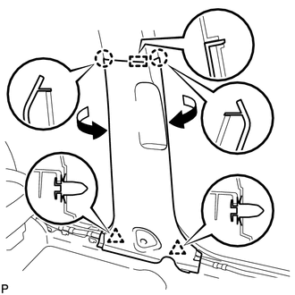
9. REMOVE LOWER CENTER PILLAR GARNISH LH
|
(a) Disengage the 2 claws, guide and 2 clips, and remove the lower center pillar garnish LH as shown in the illustration. |
|
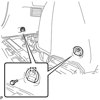
10. REMOVE UPPER CENTER PILLAR GARNISH LH
|
(a) Remove the screw. |
|
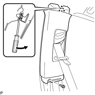
(b) Using a clip remover, disengage the clip.
(c) Pass the floor anchor of the front seat outer belt assembly LH through the upper center pillar garnish LH and remove the upper center pillar garnish LH.
11. REMOVE FRONT DOOR SCUFF PLATE RH
HINT:
Use the same procedure for the RH side and the LH side.
12. REMOVE COWL SIDE TRIM SUB-ASSEMBLY RH
HINT:
Use the same procedure for the RH side and the LH side.
13. REMOVE FRONT DOOR OPENING TRIM WEATHERSTRIP RH
HINT:
Use the same procedure for the RH side and the LH side.
14. REMOVE FRONT PILLAR GARNISH RH
HINT:
Use the same procedure for the RH side and the LH side.
15. REMOVE REAR DOOR SCUFF PLATE RH
HINT:
Use the same procedure for the RH side and the LH side.
16. REMOVE REAR DOOR OPENING TRIM WEATHERSTRIP RH
HINT:
Use the same procedure for the RH side and the LH side.
17. REMOVE LAP BELT OUTER ANCHOR COVER (for RH Side)
HINT:
Use the same procedure for the RH side and the LH side.
18. DISCONNECT FRONT SEAT OUTER BELT ASSEMBLY RH
HINT:
Use the same procedure for the RH side and the LH side.
19. REMOVE LOWER CENTER PILLAR GARNISH RH
HINT:
Use the same procedure for the RH side and the LH side.
20. REMOVE UPPER CENTER PILLAR GARNISH RH
HINT:
Use the same procedure for the RH side and the LH side.
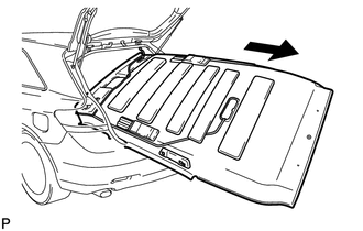
21. REMOVE TONNEAU COVER ASSEMBLY (w/ Tonneau Cover)
(a) Remove the tonneau cover assembly.
22. REMOVE DECK BOARD ASSEMBLY
|
(a) Disengage the 2 guides and remove the deck board assembly. |
|
23. REMOVE NO. 3 DECK BOARD SUB-ASSEMBLY
|
(a) Disengage the 2 guides and remove the No. 3 deck board sub-assembly. |
|
24. REMOVE DECK SIDE TRIM BOX LH
|
(a) Remove the 3 clips and remove the deck side trim box LH. |
|
25. REMOVE NO. 2 DECK BOARD SUB-ASSEMBLY
|
(a) Disengage the 2 guides and remove the No. 2 deck board sub-assembly. |
|
26. REMOVE DECK SIDE TRIM BOX RH
|
(a) Remove the 4 clips and remove the deck side trim box RH. |
|
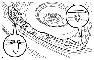
27. REMOVE NO. 1 DECK BOARD
|
(a) Disengage the 6 clips and remove the No. 1 deck board. |
|
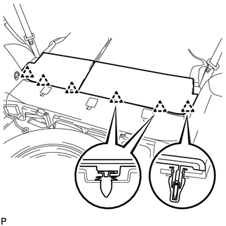
28. REMOVE REAR SEAT SUB FLOOR PANEL ASSEMBLY
|
(a) Disengage the 2 claws, 2 guides and 5 clips, and remove the rear seat sub floor panel assembly. |
|
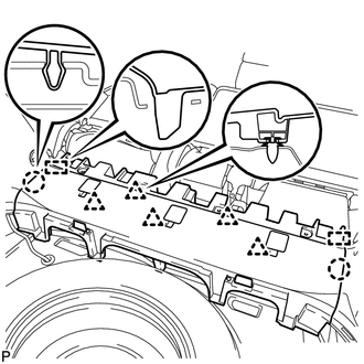
29. REMOVE REAR FLOOR FINISH PLATE
|
(a) Disengage the 2 claws and 4 clips, and remove the rear floor finish plate. |
|
30. REMOVE REAR SEAT HEADREST ASSEMBLY (for LH Side)
31. REMOVE REAR SEAT INNER TRACK BRACKET COVER (for LH Side)
32. REMOVE REAR SEAT OUTER TRACK BRACKET COVER (for LH Side)
33. DISCONNECT REAR SEAT NO. 2 RECLINING CONTROL CABLE SUB-ASSEMBLY
34. REMOVE REAR SEAT ASSEMBLY LH
35. REMOVE RECLINING REMOTE CONTROL BEZEL LH
|
(a) Using a screwdriver, disengage the 3 claws and remove the reclining remote control bezel LH. Text in Illustration
HINT: Tape the screwdriver tip before use. |
|
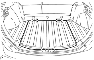
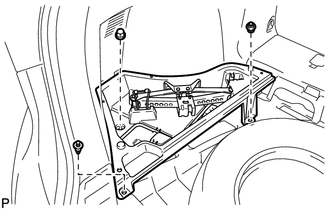
36. REMOVE LUGGAGE HOLD BELT STRIKER ASSEMBLY (for LH Side)
|
(a) Remove the 2 bolts. |
|
(b) Disengage the 2 guides and remove the 2 luggage hold belt striker assemblies.
37. DISCONNECT REAR SEAT OUTER BELT ASSEMBLY LH
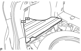
38. REMOVE DECK TRIM SIDE PANEL ASSEMBLY LH
(a) Remove the bolt and clip.
(b) Disengage the 7 claws and 5 clips.
(c) Disconnect the connector and remove the deck trim side panel assembly LH.
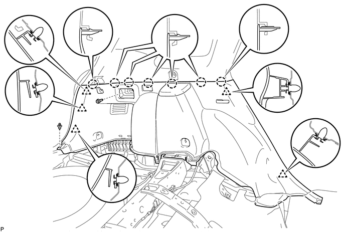
39. REMOVE ROOF SIDE INNER GARNISH ASSEMBLY LH
(a) w/ Rear Speaker:
(1) Disconnect the connector.
|
(b) Put protective tape around the 3 stud bolts. Text in Illustration
|
|
(c) Remove the bolt and disengage the 10 clips.
(d) Lift the lower edge of the roof side inner garnish assembly LH up and pull it out over the 3 stud bolts while ensuring ample clearance.
NOTICE:
Do not damage the roof headlining assembly or roof side inner garnish assembly.
(e) Pass the floor anchor of the rear seat outer belt assembly LH through the roof side inner garnish assembly LH and remove the roof side inner garnish assembly LH.
 Text in Illustration
|
*1 |
Stud Bolt |
- |
- |
40. REMOVE REAR SEAT HEADREST ASSEMBLY (for RH Side)
41. REMOVE REAR SEAT CENTER HEADREST ASSEMBLY
42. REMOVE REAR SEAT INNER TRACK BRACKET COVER (for RH Side)
43. REMOVE REAR SEAT OUTER TRACK BRACKET COVER (for RH Side)
44. DISCONNECT REAR SEAT RECLINING CONTROL CABLE SUB-ASSEMBLY
45. REMOVE REAR SEAT ASSEMBLY RH
46. REMOVE RECLINING REMOTE CONTROL BEZEL RH
HINT:
Use the same procedure for the RH side and the LH side.
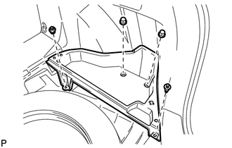
47. REMOVE LUGGAGE HOLD BELT STRIKER ASSEMBLY (for RH Side)
HINT:
Use the same procedure for the RH side and the LH side.
48. DISCONNECT REAR SEAT OUTER BELT ASSEMBLY RH
HINT:
Use the same procedure for the RH side and the LH side.
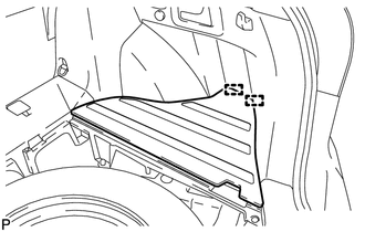
49. REMOVE DECK TRIM SIDE PANEL ASSEMBLY RH
(a) Remove the bolt and clip.
(b) Disengage the 7 claws and 6 clips.
(c) Disconnect each connector and remove the deck trim side panel assembly RH.
50. REMOVE ROOF SIDE INNER GARNISH ASSEMBLY RH
HINT:
Use the same procedure for the RH side and the LH side.
51. REMOVE MAP LIGHT ASSEMBLY
52. REMOVE VISOR BRACKET COVER (for LH Side)
|
(a) Using a moulding remover, disengage the 4 claws and remove the visor bracket cover. NOTICE: Visor bracket cover cannot be reused. |
|
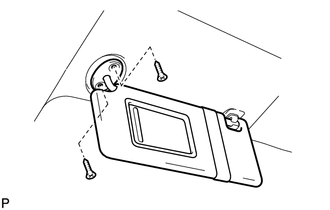
53. REMOVE VISOR ASSEMBLY LH
|
(a) Remove the 2 screws and remove the visor assembly LH. |
|
54. REMOVE VISOR BRACKET COVER (for RH Side)
HINT:
Use the same procedure for the RH side and the LH side.
55. REMOVE VISOR ASSEMBLY RH
HINT:
Use the same procedure for the RH side and the LH side.
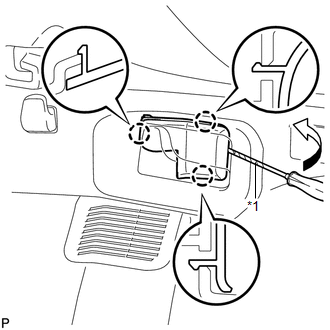
56. REMOVE INNER REAR VIEW MIRROR STAY HOLDER COVER (w/ EC Mirror)
57. REMOVE SPOT LIGHT ASSEMBLY
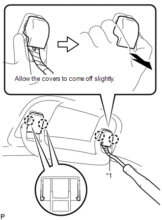
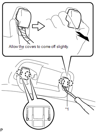
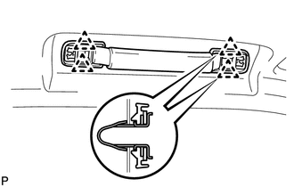
58. REMOVE ASSIST GRIP SUB-ASSEMBLY (w/o Sliding Roof)
|
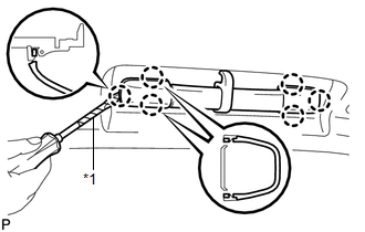
(a) Using a clip remover, disengage the 4 claws. Text in Illustration
NOTICE: Do not forcibly pry the assist grip covers to prevent them from being deformed. HINT:
|
|
|
(b) Pull off the 2 assist grip covers by hand. |
|
(c) Disengage the 2 clips and remove the front assist grip sub-assembly.
(d) Remove the 2 clips from the vehicle body.
HINT:
Use the same procedure for the RH side and the LH side.
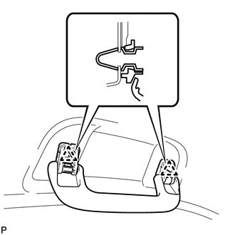
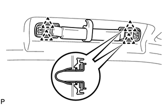
59. REMOVE REAR ASSIST GRIP ASSEMBLY (w/o Sliding Roof)
|
(a) Using a clip remover, disengage the 4 claws. Text in Illustration
NOTICE: Do not forcibly pry the assist grip covers to prevent them from being deformed. HINT:
|
|
(b) Pull off the 2 assist grip covers by hand.
|
(c) Disengage the 2 clips and remove the rear assist grip assembly. |
|
(d) Remove the 2 clips from the vehicle body.
HINT:
Use the same procedure for the RH side and the LH side.
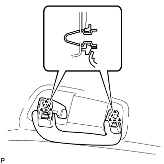
60. REMOVE ASSIST GRIP SUB-ASSEMBLY (w/ Sliding Roof)
|
(a) Using a screwdriver, disengage the 6 claws and remove the 2 assist grip covers. Text in Illustration
NOTICE: Do not forcibly pry the assist grip covers to prevent them from being deformed. HINT: Tape the screwdriver tip before use. |
|
|
(b) Disengage the 4 clips and remove the assist grip sub-assembly. |
|
(c) Remove the 4 clips from the vehicle body.
HINT:
Use the same procedure for the RH side and the LH side.
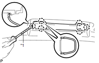
61. REMOVE REAR ASSIST GRIP ASSEMBLY (w/ Sliding Roof)
|
(a) Using a screwdriver, disengage the 6 claws and remove the 2 assist grip covers. Text in Illustration
NOTICE: Do not forcibly pry the assist grip covers to prevent them from being deformed. HINT: Tape the screwdriver tip before use. |
|
|
(b) Disengage the 4 clips and remove the rear assist grip assembly. |
|
(c) Remove the 4 clips from the vehicle body.
HINT:
Use the same procedure for the RH side and the LH side.
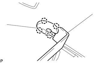
62. REMOVE VISOR HOLDER
|
(a) Turn the visor holder approximately 45° and pull it out as shown in the illustration. |
|
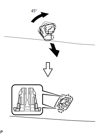
(b) Disengage the 2 claws and remove the visor holder.
HINT:
Use the same procedure for the RH side and the LH side.
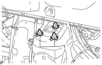
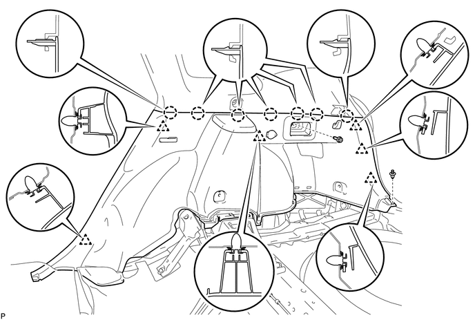
63. REMOVE ROOF HEADLINING ASSEMBLY (w/o Sliding Roof)
(a) Disconnect the No. 1 roof wire connector and disengage the 4 clamps from the front pillar LH.
(b) w/ EC Mirror:
(1) Disconnect the No. 1 roof wire connector from the inner rear view mirror.
(c) Disconnect the No. 2 antenna cord sub-assembly connector and washer hose, and disengage the 5 clamps from the front pillar RH.
(d) Disconnect the No. 2 antenna cord sub-assembly connector and washer hose from the rear pillar RH.
(e) Remove the 3 clips.
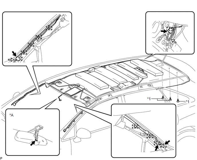 Text in Illustration
|
*A |
w/ EC Mirror |
- |
- |
|
*1 |
Clip |
- |
- |
|
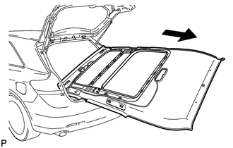
(f) Remove the roof headlining assembly from the vehicle through the back door. NOTICE: Do not damage the roof headlining assembly or body interior. |
|
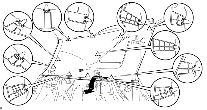
64. REMOVE ROOF HEADLINING ASSEMBLY (w/ Sliding Roof)
(a) Disconnect the No. 1 roof wire connectors and disengage the 4 clamps from the front pillar LH.
(b) Disconnect the No. 1 roof wire connector from the inner rear view mirror.
(c) Disconnect the No. 2 antenna cord sub-assembly connector and washer hose, and disengage the 5 clamps from the front pillar RH.
(d) Disconnect the No. 2 antenna cord sub-assembly connector and washer hose from the rear pillar RH.
(e) Remove the 3 clips.
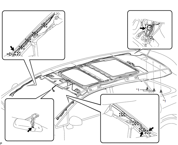 Text in Illustration
|
*1 |
Clip |
- |
- |
(f) Disengage the 23 fasteners.
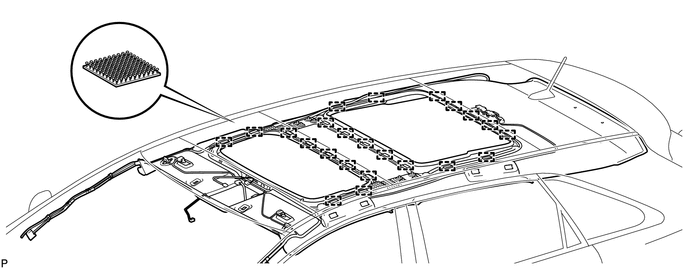
|
(g) Remove the roof headlining assembly from the vehicle through the back door. NOTICE: Do not damage the roof headlining assembly or body interior. |
|
 Disassembly
DISASSEMBLY
PROCEDURE
1. REMOVE NO. 2 ANTENNA CORD SUB-ASSEMBLY (w/o Sliding Roof)
2. REMOVE NO. 2 ANTENNA CORD SUB-ASSEMBLY (w/ Sliding Roof)
3. REMOVE VANITY LIGHT ASSEMBLY
(a) Remove the ...
 Reassembly
REASSEMBLY
PROCEDURE
1. INSTALL NO. 14 ROOF SILENCER PAD
(a) Align the markings on the roof headlining assembly with the No. 14 roof silencer
pad and install the silencer pad using hot-melt glue ...
Other materials about Toyota Venza:
On-vehicle Inspection
ON-VEHICLE INSPECTION
PROCEDURE
1. INSPECT CENTER AIRBAG SENSOR ASSEMBLY (VEHICLE NOT INVOLVED IN COLLISION)
(a) Perform a diagnostic system check (See page
).
2. INSPECT CENTER AIRBAG SENSOR ASSEMBLY (VEHICLE INVOLVED IN COLLISION AND AIRBAG
HAS NOT D ...
Crankshaft Position Sensor
Components
COMPONENTS
ILLUSTRATION
Removal
REMOVAL
PROCEDURE
1. REMOVE FRONT FENDER APRON SEAL RH
2. REMOVE CRANKSHAFT POSITION SENSOR
(a) Disconnect the sensor connector.
(b) Remove the bolt and sensor.
Inspection
INSPECTION
PROCEDURE ...
USB Audio System Recognition/Play Error
DESCRIPTION
When a USB device or "iPod" is connected to the USB jack of the No. 1 stereo
jack adapter assembly, it must have playable files. The device must also communicate
with and be recognized by the navigation receiver assembly. This diagno ...

0.1363