Toyota Venza: Lost Communication with AFS LIN (B124D)
DESCRIPTION
The DTC is stored when the main body ECU (driver side junction block assembly) detects malfunctions in the LIN communication system.
|
DTC No. |
DTC Detection Condition |
Trouble Area |
|---|---|---|
|
B124D |
Malfunction in LIN communication system |
|
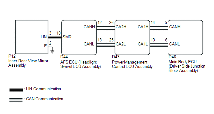
WIRING DIAGRAM
CAUTION / NOTICE / HINT
NOTICE:
First perform the communication function inspections in How to Proceed with Troubleshooting to confirm that there are no CAN communication malfunctions before troubleshooting this symptom.
PROCEDURE
|
1. |
CHECK FOR DTC |
(a) Clear the DTCs (See page .gif) ).
).
(b) Check for DTCs (See page ).
OK:
DTC B124D is not output.
| OK | .gif) |
USE SIMULATION METHOD TO CHECK |
|
.gif)
|
2. |
CHECK HARNESS AND CONNECTOR (AFS ECU - INNER REAR VIEW MIRROR ASSEMBLY) |
(a) Disconnect the D44 AFS ECU (headlight swivel ECU assembly) connector.
(b) Disconnect the P12 inner rear view mirror assembly connector.
(c) Measure the resistance according to the value(s) in the table below.
Standard Resistance:
|
Tester Connection |
Condition |
Specified Condition |
|---|---|---|
|
D44-10 (SMR) - P12-3 (LIN) |
Always |
Below 1 Ω |
|
P12-3 (LIN) - Body ground |
Always |
10 kΩ or higher |
| NG | |
REPAIR OR REPLACE HARNESS OR CONNECTOR |
|
|
3. |
INSPECT AFS ECU (HEADLIGHT SWIVEL ECU ASSEMBLY) |
(a) Reconnect the D44 AFS ECU (headlight swivel ECU assembly) connector.
|
(b) Connect an oscilloscope to the P12 inner rear view mirror assembly connector. |
|
.png)
|
(c) Check the waveform. OK:
|
|
.png)
| OK | |
REPLACE INNER REAR VIEW MIRROR ASSEMBLY |
| NG | |
REPLACE AFS ECU (HEADLIGHT SWIVEL ECU ASSEMBLY) |
 Automatic High Beam Camera (B124C)
DESCRIPTION
The DTC is stored when the main body ECU (driver side junction block assembly)
detects malfunctions in the camera (inner rear view mirror assembly).
DTC No.
DTC D ...
 Steering Position Sensor Malfunction (B2414)
DESCRIPTION
The AFS ECU (headlight swivel ECU assembly) receives signals indicating the swerve-angle
from the steering angle sensor using CAN communication.
DTC No.
DTC Detec ...
Other materials about Toyota Venza:
Installation
INSTALLATION
PROCEDURE
1. INSTALL STEERING INTERMEDIATE SHAFT ASSEMBLY
(a) Align the matchmarks on the steering intermediate shaft assembly
and the steering column assembly.
Text in Illustration
*1
Matc ...
IG Power Source Circuit
DESCRIPTION
The main power source is supplied to the A/C amplifier when the ignition switch
is ON.
The power source is used for operating the A/C amplifier and servo motor, etc.
WIRING DIAGRAM
CAUTION / NOTICE / HINT
NOTICE:
Inspect the fuses for cir ...
Checking and replacing fuses
If any of the electrical components do not operate, a fuse may have blown.
If this happens, check and replace the fuses as necessary.
Vehicles with smart key system:
Turn the “ENGINE START STOP” switch off.
Vehicles without smart key system:
Turn th ...

0.1374