Toyota Venza: Installation
INSTALLATION
PROCEDURE
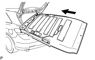
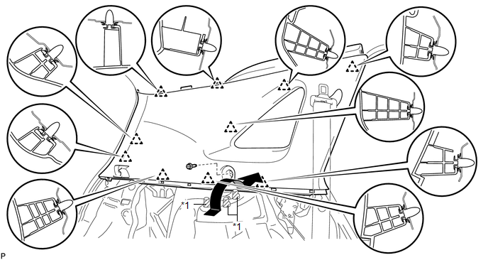
1. INSTALL ROOF HEADLINING ASSEMBLY (w/o Sliding Roof)
|
(a) Pull the roof headlining assembly into the vehicle through the back door. NOTICE: Do not damage the roof headlining assembly or body interior. |
|
(b) Install the 3 clips.
(c) Connect the No. 2 antenna cord sub-assembly connector and washer hose to the rear pillar RH.
(d) Connect the No. 2 antenna cord sub-assembly connectors and washer hose, and engage the 5 clamps to the front pillar RH.
(e) w/ EC Mirror:
(1) Connect the No. 1 roof wire connector to the inner rear view mirror.
(f) Connect the No. 1 roof wire connectors and engage the 4 clamps to the front pillar LH.
.png) Text in Illustration
Text in Illustration
|
*A |
w/ EC Mirror |
- |
- |
|
*1 |
Clip |
- |
- |
NOTICE:
After installation, make sure that the back door weatherstrip does not interfere with the roof headlining assembly.
2. INSTALL ROOF HEADLINING ASSEMBLY (w/ Sliding Roof)
|
(a) Pull the roof headlining assembly into the vehicle through the back door. NOTICE: Do not damage the roof headlining assembly or body interior. |
|
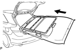
(b) Engage the 23 fasteners.
.png)
(c) Install the 3 clips.
(d) Connect the No. 2 antenna cord sub-assembly connector and washer hose to the rear pillar RH.
(e) Connect the No. 2 antenna cord sub-assembly connector and washer hose, and engage the 5 clamps to the front pillar RH.
(f) Connect the No. 1 roof wire connector to the inner rear view mirror.
(g) Connect the No. 1 roof wire connectors and engage the 4 clamps to the front pillar LH.
.png) Text in Illustration
Text in Illustration
|
*1 |
Clip |
- |
- |
NOTICE:
After installation, make sure that the back door weatherstrip does not interfere with the roof headlining assembly.
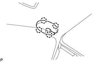
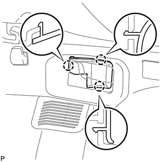
3. INSTALL VISOR HOLDER
|
(a) Engage the 2 claws. |
|
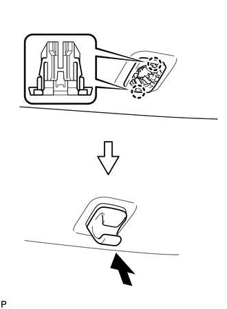
(b) Push in the visor holder as shown in the illustration.
HINT:
Use the same procedure for the RH side and the LH side.
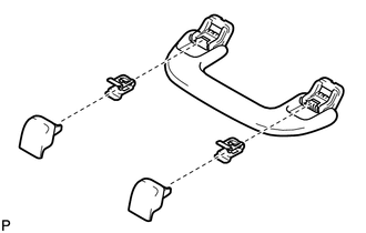
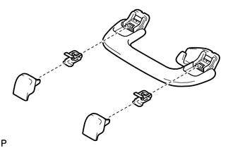
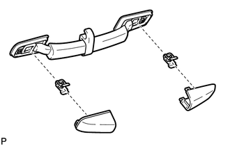
4. INSTALL ASSIST GRIP SUB-ASSEMBLY (w/o Sliding Roof)
|
(a) Assemble the assist grip sub-assembly as shown in the illustration. |
|
|
(b) Install the assist grip sub-assembly. HINT: Use the same procedure for the RH side and the LH side. |
|
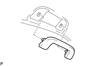
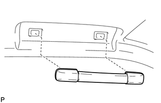
5. INSTALL REAR ASSIST GRIP ASSEMBLY (w/o Sliding Roof)
|
(a) Assemble the rear assist grip assembly as shown in the illustration. |
|
|
(b) Install the rear assist grip assembly. HINT: Use the same procedure for the RH side and the LH side. |
|
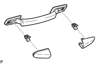
6. INSTALL ASSIST GRIP SUB-ASSEMBLY (w/ Sliding Roof)
|
(a) Assemble the assist grip sub-assembly as shown in the illustration. |
|
|
(b) Install the assist grip sub-assembly. HINT: Use the same procedure for the RH side and the LH side. |
|
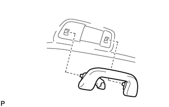
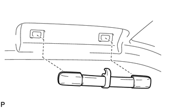
7. INSTALL REAR ASSIST GRIP ASSEMBLY (w/ Sliding Roof)
|
(a) Assemble the rear assist grip assembly as shown in the illustration. |
|
|
(b) Install the rear assist grip assembly. HINT: Use the same procedure for the RH side and the LH side. |
|
8. INSTALL SPOT LIGHT ASSEMBLY
.gif)
9. INSTALL INNER REAR VIEW MIRROR STAY HOLDER COVER (w/ EC Mirror)
10. INSTALL VISOR ASSEMBLY LH
|
(a) Install the visor assembly LH with the 2 screws. |
|
.png)
11. INSTALL VISOR BRACKET COVER (for LH Side)
|
(a) Engage the 4 claws and install a new visor bracket cover. |
|
12. INSTALL VISOR ASSEMBLY RH
HINT:
Use the same procedure for the RH side and the LH side.
13. INSTALL VISOR BRACKET COVER (for RH Side)
HINT:
Use the same procedure for the RH side and the LH side.
14. INSTALL MAP LIGHT ASSEMBLY
15. INSTALL ROOF SIDE INNER GARNISH ASSEMBLY LH
(a) Pass the floor anchor of the rear seat outer belt assembly LH through the roof side inner garnish assembly LH.
(b) Insert the upper edge of the roof side inner garnish assembly LH into the roof headlining. Lift the lower edge of the garnish up and push it in over the 3 stud bolts while ensuring ample clearance.
NOTICE:
Do not damage the roof headlining assembly or roof side inner garnish assembly.
(c) Engage the 10 clips to install the roof side inner garnish assembly LH with the bolt.
 Text in Illustration
|
*1 |
Stud Bolt |
- |
- |
|
(d) Remove the applied protective tape. Text in Illustration
|
|
.png)
(e) w/ Rear Speaker:
(1) Disconnect the connector.
16. INSTALL DECK TRIM SIDE PANEL ASSEMBLY LH
(a) Connect the connector.
(b) Engage the 7 claws and the 5 clips.
(c) Install the deck trim side panel assembly LH with the bolt and clip.
.png)
17. CONNECT REAR SEAT OUTER BELT ASSEMBLY LH
18. INSTALL LUGGAGE HOLD BELT STRIKER ASSEMBLY (for LH Side)
|
(a) Engage the 2 guides. |
|
.png)
(b) Install the 2 luggage hold belt striker assemblies with the 2 bolts.
19. INSTALL RECLINING REMOTE CONTROL BEZEL LH
|
(a) Engage the 3 claws to install the reclining remote control bezel LH. |
|
20. INSTALL REAR SEAT ASSEMBLY LH
21. INSTALL REAR SEAT NO. 2 RECLINING CONTROL CABLE SUB-ASSEMBLY
22. INSTALL REAR SEAT OUTER TRACK BRACKET COVER (for LH Side)
23. INSTALL REAR SEAT INNER TRACK BRACKET COVER (for LH Side)
24. INSTALL REAR SEAT HEADREST ASSEMBLY (for LH Side)
25. INSTALL ROOF SIDE INNER GARNISH ASSEMBLY RH
HINT:
Use the same procedure for the RH side and the LH side.
26. INSTALL DECK TRIM SIDE PANEL ASSEMBLY RH
(a) Connect each connector.
(b) Engage the 7 claws and the 6 clips.
(c) Install the deck trim side panel assembly RH with the bolt and clip.
.png)
27. CONNECT REAR SEAT OUTER BELT ASSEMBLY RH
HINT:
Use the same procedure for the RH side and the LH side.
28. INSTALL LUGGAGE HOLD BELT STRIKER ASSEMBLY (for RH Side)
HINT:
Use the same procedure for the RH side and the LH side.
29. INSTALL RECLINING REMOTE CONTROL BEZEL RH
HINT:
Use the same procedure for the RH side and the LH side.
30. INSTALL REAR SEAT ASSEMBLY RH
31. INSTALL REAR SEAT RECLINING CONTROL CABLE SUB-ASSEMBLY (for RH Side)
32. INSTALL REAR SEAT OUTER TRACK BRACKET COVER (for RH Side)
33. INSTALL REAR SEAT INNER TRACK BRACKET COVER (for RH Side)
34. INSTALL REAR SEAT CENTER HEADREST ASSEMBLY
35. INSTALL REAR SEAT HEADREST ASSEMBLY (for RH Side)
36. INSTALL REAR FLOOR FINISH PLATE
|
(a) Engage the 4 clips and 2 claws to install the rear floor finish plate. |
|
.png)
37. INSTALL REAR SEAT SUB FLOOR PANEL ASSEMBLY
|
(a) Engage the 2 guides, 2 claws and 5 clips to install the rear seat sub floor panel assembly. |
|
.png)
38. INSTALL NO. 1 DECK BOARD
|
(a) Engage the 6 clips to install the No. 1 deck board. |
|
.png)
39. INSTALL DECK SIDE TRIM BOX RH
|
(a) Install the deck side trim box RH with the 4 clips. |
|
.png)
40. INSTALL NO. 2 DECK BOARD SUB-ASSEMBLY
|
(a) Engage the 2 guides to install the No. 2 deck board sub-assembly. |
|
.png)
41. INSTALL DECK SIDE TRIM BOX LH
|
(a) Install the deck side trim box LH with the 3 clips. |
|
.png)
42. INSTALL NO. 3 DECK BOARD SUB-ASSEMBLY
|
(a) Engage the 2 guides to install the No. 3 deck board sub-assembly. |
|
.png)
43. INSTALL DECK BOARD ASSEMBLY
|
(a) Engage the 2 guides to install the deck board assembly. |
|
.png)
44. INSTALL TONNEAU COVER ASSEMBLY (w/ Tonneau Cover)
(a) Install the tonneau cover assembly.
45. INSTALL UPPER CENTER PILLAR GARNISH LH
(a) Pass the floor anchor of the front seat outer belt assembly LH through the upper center pillar garnish LH.
|
(b) Engage the clip. |
|
(c) Install the upper center pillar garnish LH with the screw.
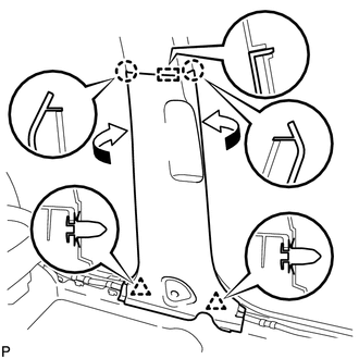
46. INSTALL LOWER CENTER PILLAR GARNISH LH
|
(a) Engage the guide, 2 claws and the 2 clips to install the lower center pillar garnish LH as shown in the illustration. |
|
47. CONNECT FRONT SEAT OUTER BELT ASSEMBLY LH
48. INSTALL LAP BELT OUTER ANCHOR COVER (for LH Side)
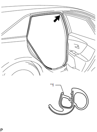
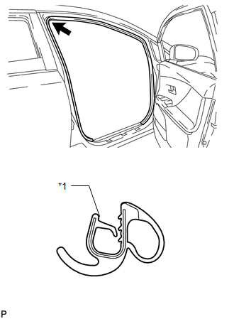
49. INSTALL REAR DOOR OPENING TRIM WEATHERSTRIP LH
|
(a) Align the alignment mark (Purple) on the weatherstrip with the protruding portion on the body indicated by the arrow in the illustration, and install the rear door opening trim weatherstrip LH. Text in Illustration
NOTICE: After installation, check that the corners fit correctly. |
|
50. INSTALL REAR DOOR SCUFF PLATE LH
|
(a) Engage the 2 clips and 6 claws to install the rear door scuff plate LH. |
|
.png)
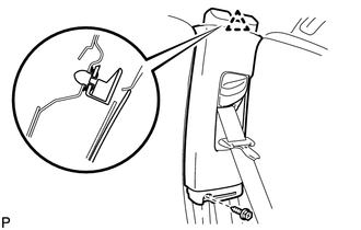
51. INSTALL FRONT PILLAR GARNISH LH
|
(a) Engage the 3 guides. |
|
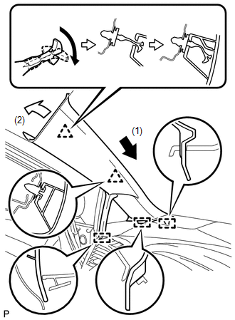
(b) Turn the end of the front pillar garnish clip 90° with needle-nosed pliers and install it to the front pillar garnish RH.
HINT:
Tape the needle-nosed pliers tips before use.
(c) Engage the 2 clips to install the front pillar garnish LH.
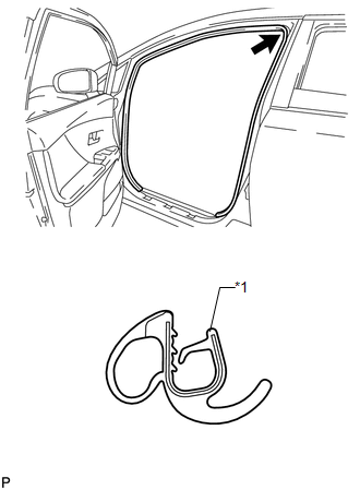
52. INSTALL FRONT DOOR OPENING TRIM WEATHERSTRIP LH
|
(a) Align the alignment mark (Yellow) on the weatherstrip with the protruding portion on the body indicated by the arrow in the illustration, and install the front door opening trim weatherstrip LH. Text in Illustration
NOTICE: After installation, check that the corners fit correctly. |
|
53. INSTALL COWL SIDE TRIM SUB-ASSEMBLY LH
|
(a) Engage the 2 clips to install the cowl side trim sub-assembly LH. |
|
.png)
(b) Install the clip.
54. INSTALL FRONT DOOR SCUFF PLATE LH
|
(a) Engage the guide, 3 clips and the 7 claws to install the front door scuff plate LH. |
|
.png)
55. INSTALL UPPER CENTER PILLAR GARNISH RH
HINT:
Use the same procedure for the RH side and the LH side.
56. INSTALL LOWER CENTER PILLAR GARNISH RH
HINT:
Use the same procedure for the RH side and the LH side.
57. CONNECT FRONT SEAT OUTER BELT ASSEMBLY RH
HINT:
Use the same procedure for the RH side and the LH side.
58. INSTALL LAP BELT OUTER ANCHOR COVER (for RH Side)
HINT:
Use the same procedure for the RH side and the LH side.
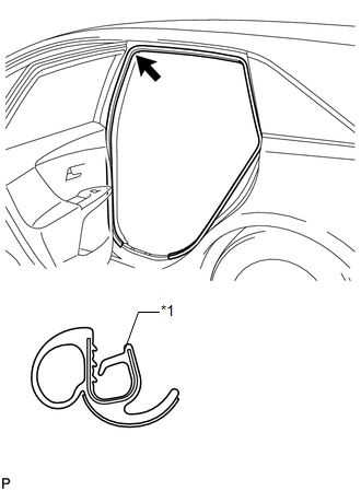
59. INSTALL REAR DOOR OPENING TRIM WEATHERSTRIP RH
|
(a) Align the alignment mark (Pink) on the weatherstrip with the protruding portion on the body indicated by the arrow in the illustration, and install the rear door opening trim weatherstrip RH. Text in Illustration
NOTICE: After installation, check that the corners fit correctly. |
|
60. INSTALL REAR DOOR SCUFF PLATE RH
HINT:
Use the same procedure for the RH side and the LH side.
61. INSTALL FRONT PILLAR GARNISH RH
HINT:
Use the same procedure for the RH side and the LH side.
62. INSTALL FRONT DOOR OPENING TRIM WEATHERSTRIP RH
|
(a) Align the alignment mark (White) on the weatherstrip with the protruding portion on the body indicated by the arrow in the illustration, and install the front door opening trim weatherstrip RH. Text in Illustration
NOTICE: After installation, check that the corners fit correctly. |
|
63. INSTALL COWL SIDE TRIM SUB-ASSEMBLY RH
HINT:
Use the same procedure for the RH side and the LH side.
64. INSTALL FRONT DOOR SCUFF PLATE RH
HINT:
Use the same procedure for the RH side and the LH side.
 Reassembly
REASSEMBLY
PROCEDURE
1. INSTALL NO. 14 ROOF SILENCER PAD
(a) Align the markings on the roof headlining assembly with the No. 14 roof silencer
pad and install the silencer pad using hot-melt glue ...
 Lighting (int)
...
Other materials about Toyota Venza:
How To Proceed With Troubleshooting
CAUTION / NOTICE / HINT
HINT:
Use this procedure to troubleshoot the theft deterrent system.
*: Use the Techstream.
PROCEDURE
1.
VEHICLE BROUGHT TO WORKSHOP
NEXT
...
Weight limits
• The gross trailer weight must never exceed TWR described in the table. • The
gross combination weight must never exceed the GCWR described in the table.
• The gross vehicle weight must never exceed the GVWR indicated on the Certification
Label. ...
Terminals Of Ecu
TERMINALS OF ECU
HINT:
Check from the rear of the connector while it is connected to the components.
1. RADIO AND DISPLAY RECEIVER ASSEMBLY
Terminal No. (Symbol)
Wiring Color
Terminal Description
Condition
...

0.1386