Toyota Venza: Parts Location
PARTS LOCATION
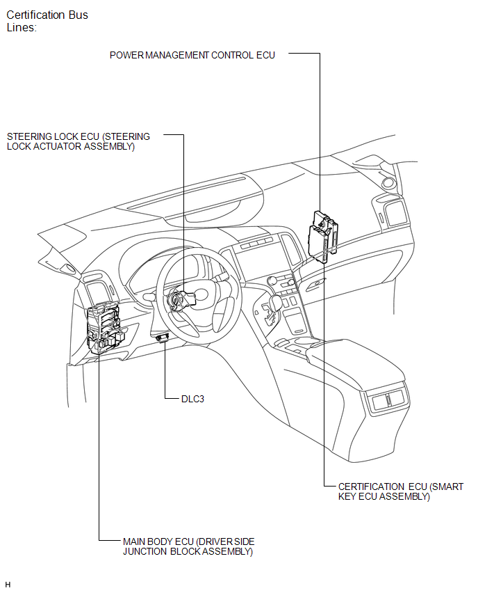
ILLUSTRATION
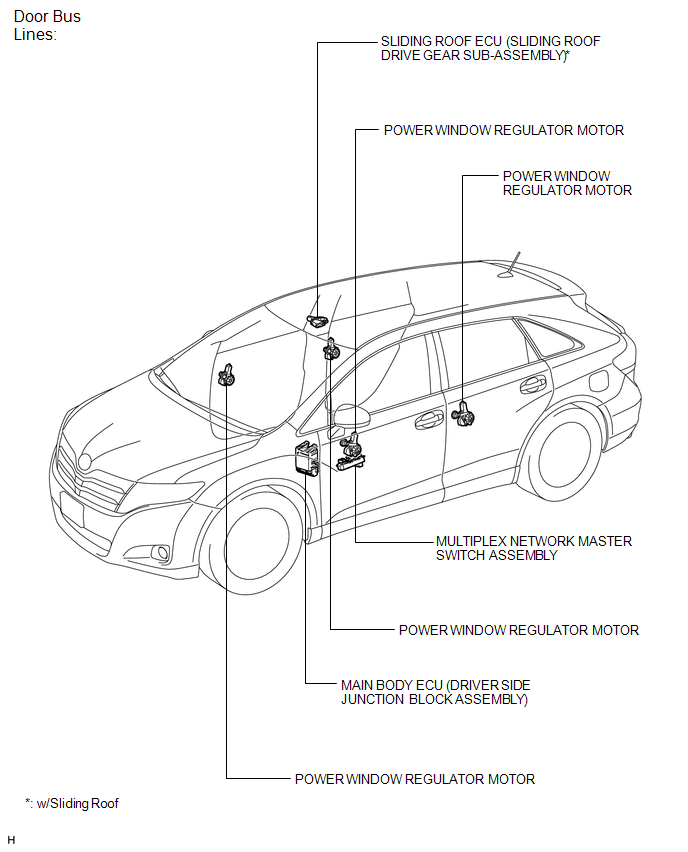
ILLUSTRATION
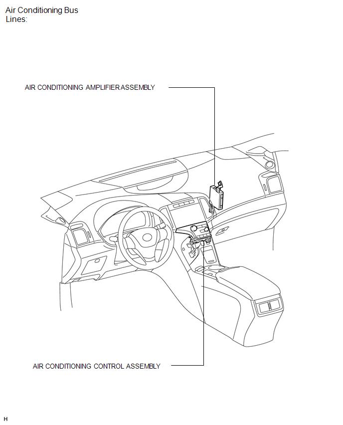
ILLUSTRATION
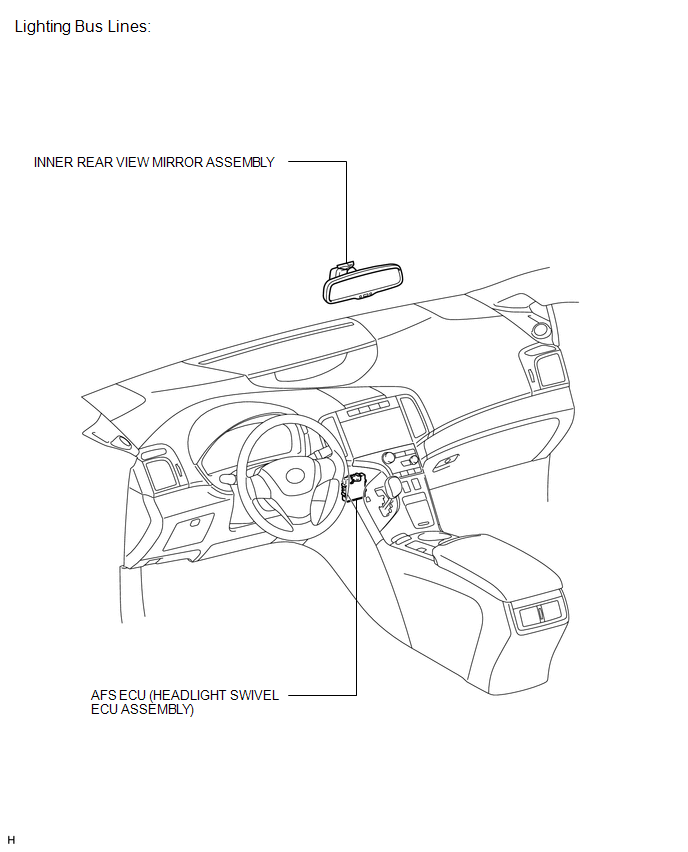
ILLUSTRATION
 Precaution
PRECAUTION
NOTICE:
When disconnecting the cable from the negative (-) battery terminal, initialize
the following systems after the cable is reconnected.
System Name
See Proc ...
 System Description
SYSTEM DESCRIPTION
1. LIN COMMUNICATION SYSTEM DESCRIPTION
The LIN communication system is used for communication between the components
in the table below. If communication cannot be performed th ...
Other materials about Toyota Venza:
Speaker Circuit
DESCRIPTION
for 6 Speakers:
If there is a short in a speaker circuit, the navigation receiver assembly detects
it and stops output to the speakers.
Thus sound cannot be heard from the speakers even if there is no malfunction
in the navigation receiver a ...
Installation
INSTALLATION
PROCEDURE
1. INSTALL DRIVE MONITOR SWITCH
(a) Engage the 4 claws to install the drive monitor switch.
2. INSTALL RADIO AND DISPLAY RECEIVER ASSEMBLY WITH BRACKET (for Radio and Display
Type)
3. INSTALL NAVIGATION RECEIVER ASSEMBLY WITH B ...
Cruise SET Indicator Light Circuit
DESCRIPTION
The ECM detects a cruise control switch signal and sends it to the combination
meter assembly through CAN. Then the SET indicator light comes on.
The SET indicator light circuit uses CAN for communication. If there
is a malfunct ...

0.172