Toyota Venza: Adjustment
ADJUSTMENT
PROCEDURE
1. INSPECT AND ADJUST BRAKE PEDAL HEIGHT
(a) Check the brake pedal height.
(1) Turn back the carpet.
|
(2) Measure the brake pedal height from the dash panel to the bottom edge of the brake pedal pad. Text in Illustration
Standard pedal height: 135 to 145 mm (5.31 to 5.71 in.) If pedal height is incorrect, adjust the push rod length according to procedure below. |
|
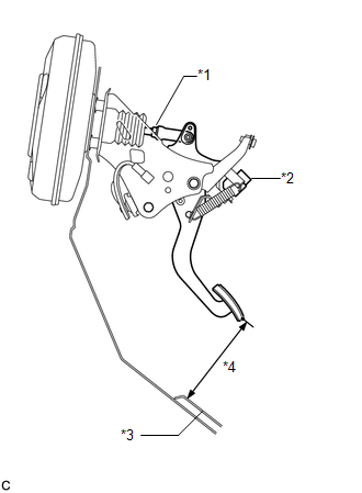
(b) Adjust the push rod length.
(1) Remove the stop light switch assembly (See page
.gif) ).
).
(2) Remove the brake booster assembly (See page
).
|
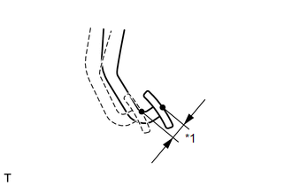
(3) Loosen the lock nut and adjust the push rod length*1 shown in the illustration by turning the brake master cylinder push rod clevis to achieve the length*1. Text in Illustration
Length*1: 155.1 to 156.1 mm (6.11 to 6.15 in.) |
|
.png)
(4) Tighten the lock nut.
Torque:
26 N·m {265 kgf·cm, 19 ft·lbf}
(5) Install the brake booster assembly (See page
).
If the pedal height is incorrect even if the push rod length is adjusted, check that there is no damage to the brake pedal support assembly and dash panel.
- Even if there is damage, there is no problem if the reserve distance is within the standard value.
- If necessary, replace the brake pedal support assembly.
(6) Install the stop light switch assembly (See page
).
(7) Check that the stop lights do not come on when the brake pedal is released.
(c) After adjusting the pedal height, check the brake pedal free play.
2. INSPECT BRAKE PEDAL FREE PLAY
(a) Stop the engine and firmly depress the brake pedal several times until no vacuum is left in the booster.
|
(b) Measure the free play of the brake pedal. Text in Illustration
Standard pedal free play: 1.0 to 3.0 mm (0.0394 to 0.118 in.) If the pedal free play is not as specified, check the stop light switch
clearance (See page |
|
3. INSPECT BRAKE PEDAL RESERVE DISTANCE
HINT:
Measure the distance at the same point used for the brake pedal height inspection.
(a) Start the engine.
(b) Depress the brake pedal and check the pedal reserve distance.
(1) Depress the brake pedal with a force of 500 N (51 kgf, 112.4 lbf).
(2) Measure the distance between the brake pedal and dash panel.
Standard pedal reserve distance:
28 mm (1.10 in.)
If the distance is not as specified, troubleshoot the brake system (See page
).
 Disassembly
DISASSEMBLY
PROCEDURE
1. REMOVE BRAKE PEDAL RETURN SPRING
(a) Remove the brake pedal return spring from the brake pedal support
assembly.
...
 Reassembly
REASSEMBLY
PROCEDURE
1. INSTALL STOP LIGHT SWITCH CUSHION
(a) Install the stop light switch cushion to the brake pedal support assembly.
2. INSTALL BRAKE PEDAL PAD
(a) Install the brake pedal pad ...
Other materials about Toyota Venza:
Intake Manifold Runner Position Sensor / Switch Circuit (Bank 1) (P2014,P2016,P2017)
DESCRIPTION
The tumble control valve position sensor is a non-contact type sensor.
The position sensor measures the opening angle of the tumble control valve. The
sensor is reliable and accurate, as it is electrically controlled by Hall elements.
...
System Diagram
SYSTEM DIAGRAM
Communication Table
Sender
Receiver
Signal
Line
ECM
Combination Meter ECU
CRUISE main indicator operation signal
SET indicator operation sig ...
Brake Signal Malfunction (B2284)
DESCRIPTION
The power management control ECU receives brake signal information from 2 sources.
It receives a signal from the stop light switch assembly via a direct line, and
a signal from the ECM via CAN. If the information from these 2 sources is incons ...

0.1311