Toyota Venza: Wireless Door Lock Tuner Circuit Malfunction (B1242)
DESCRIPTION
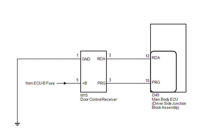
The door control receiver receives signals from the transmitter and sends these signals to the main body ECU (driver side junction block assembly).
|
DTC No. |
DTC Detection Condition |
Trouble Area |
|---|---|---|
|
B1242 |
In diagnostic mode, an applicable RDA signal cannot be received within 2.4 seconds after a PRG signal has been output from the main body ECU (driver side junction block assembly). |
|
WIRING DIAGRAM
PROCEDURE
|
1. |
CHECK HARNESS AND CONNECTOR (MAIN BODY ECU - DOOR CONTROL RECEIVER) |
|
(a) Disconnect the D49 main body ECU connector and the M15 door control receiver connector. |
|
(b) Measure the resistance according to the value(s) in the table below.
Standard Resistance:
|
Tester Connection |
Condition |
Specified Condition |
|---|---|---|
|
D49-12 (RDA) - M15-2 (RDA) |
Always |
Below 1 Ω |
|
D49-12 (RDA) - Body ground |
Always |
10 kΩ or higher |
|
D49-10 (PRG) - M15-3 (PRG) |
Always |
Below 1 Ω |
|
D49-10 (PRG) - Body ground |
Always |
10 kΩ or higher |
|
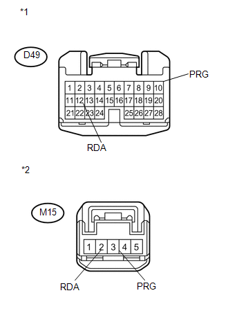
*1 |
Front view of wire harness connector (to Main Body ECU (Driver Side Junction Block Assembly)) |
|
*2 |
Front view of wire harness connector (to Door Control Receiver) |
| NG | .gif) |
REPAIR OR REPLACE HARNESS OR CONNECTOR |
|
.gif)
|
2. |
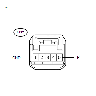
CHECK HARNESS AND CONNECTOR (BATTERY, BODY GROUND) |
|
(a) Measure the voltage and resistance according to the value(s) in the table below. Standard:
|
|
| NG | |
REPAIR OR REPLACE HARNESS OR CONNECTOR |
|
|
3. |
REPLACE DOOR CONTROL RECEIVER |
(a) Temporarily replace the door lock control receiver with a new or known good
one (See page .gif) ).
).
|
|
4. |
REGISTER RECOGNITION CODE |
(a) Perform the Registration procedure (See page
).
|
|
5. |
CONFIRM DTC |
(a) Clear the DTCs (See page ).
(b) Recheck for DTCs.
|
Result |
Proceed to |
|---|---|
|
DTC is not output |
A |
|
DTC is output |
B |
| A | |
END (DOOR CONTROL RECEIVER WAS DEFECTIVE) |
| B | |
REPLACE MAIN BODY ECU (DRIVER SIDE JUNCTION BLOCK ASSEMBLY) |
 Diagnostic Trouble Code Chart
DIAGNOSTIC TROUBLE CODE CHART
HINT:
If a trouble code is output during the DTC check, inspect the trouble areas listed
for that code. For details of the code, refer to "See page" in the ...
 Only Wireless Control Function is Inoperative
DESCRIPTION
The door control receiver receives signals from the transmitter and sends these
signals to the main body ECU. The main body ECU then controls all doors by sending
lock/unlock signals ...
Other materials about Toyota Venza:
Removal
REMOVAL
PROCEDURE
1. REMOVE REAR SEAT HEADREST ASSEMBLY
2. REMOVE REAR SEAT CENTER HEADREST ASSEMBLY
3. REMOVE REAR SEAT INNER TRACK BRACKET COVER
4. REMOVE REAR SEAT OUTER TRACK BRACKET COVER
5. DISCONNECT REAR SEAT RECLINING CONTROL CABLE S ...
Installation
INSTALLATION
PROCEDURE
1. INSTALL SHIFT LEVER ASSEMBLY
NOTICE:
Check that the park/neutral position switch and the shift lever are in neutral.
(a) Slide the slider of the transmission control cable in the direction
indicated by the arrow an ...
Registration
REGISTRATION
PROCEDURE
1. DESCRIPTION OF CODE REGISTRATION
It is necessary to register the transmitter IDs in the tire pressure warning
ECU when replacing a tire pressure warning valve and transmitter and/or a tire pressure
warning ECU.
Prepare all tra ...

0.1556