Toyota Venza: Parts Location
PARTS LOCATION
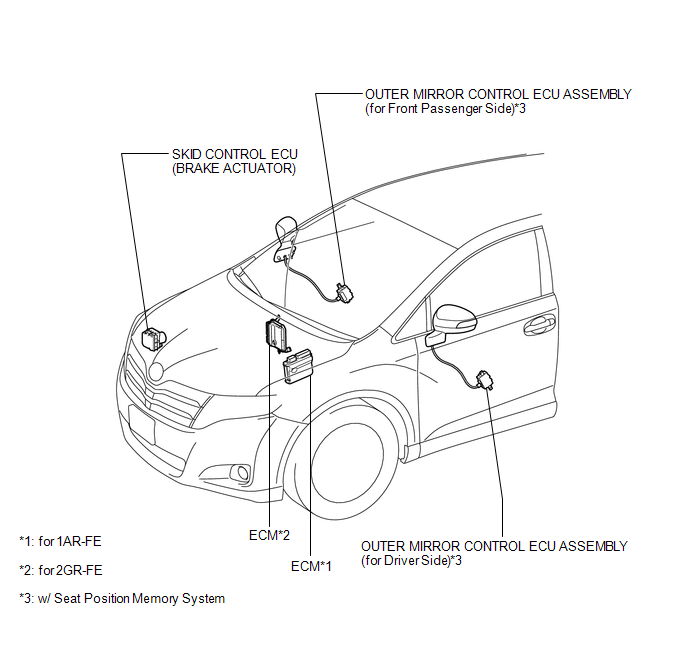
ILLUSTRATION
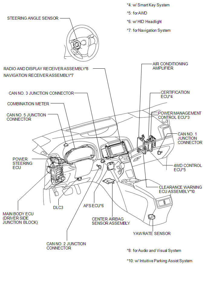
ILLUSTRATION
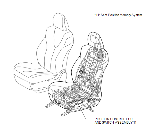
ILLUSTRATION
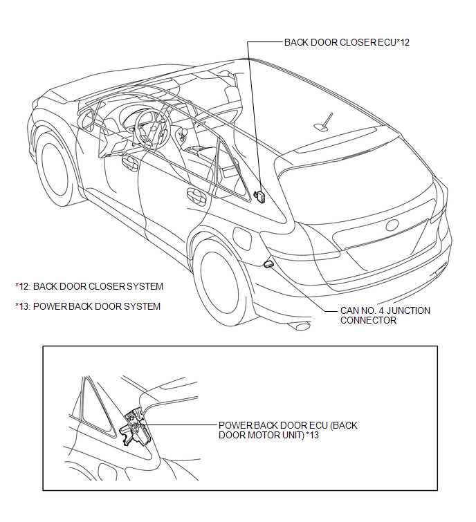
ILLUSTRATION

 Precaution
PRECAUTION
1. PRECAUTION FOR DISCONNECTING BATTERY CABLE
NOTICE:
When disconnecting the cable from the negative (-) battery terminal, initialize
the following systems after the cable is reconnect ...
Other materials about Toyota Venza:
Front Passenger Side Door Entry Lock Function does not Operate
DESCRIPTION
If the front passenger door entry unlock function operates normally, but its
entry lock function does not, this means that the request code from the front passenger
door is being output normally. In this case, a malfunction in the lock sensor ...
Charge Warning Light Comes ON while Driving
PROCEDURE
1.
CHECK LOCK FUNCTION OF GENERATOR CLUTCH PULLEY
(a) Check the lock function with the pulley installed in the vehicle.
(1) Visually check that the rotor in the generator operates with the engine running.
(b) Check ...
Fail-safe Chart
FAIL-SAFE CHART
If a problem occurs in the power steering system, the power steering assist will
be stopped or the amount of power assist will be decreased to protect the system.
Power Steering System
Malfunction
Fail-safe Operation
...

0.1439