Toyota Venza: Occupant Classification Ecu
Components
COMPONENTS
ILLUSTRATION
ILLUSTRATION

On-vehicle Inspection
ON-VEHICLE INSPECTION
CAUTION / NOTICE / HINT
CAUTION:
Be sure to follow the correct removal and installation procedures of the occupant classification ECU.
PROCEDURE
1. INSPECT OCCUPANT CLASSIFICATION ECU (VEHICLE NOT INVOLVED IN COLLISION)
(a) Perform a diagnostic system check (See page
.gif) ).
).
2. INSPECT OCCUPANT CLASSIFICATION ECU (VEHICLE INVOLVED IN COLLISION)
(a) Perform a diagnostic system check (See page
).
(b) Even if an airbag was not deployed, check if there is any damage to the occupant classification ECU. If there are any defects as mentioned below, replace the occupant classification ECU with a new one:
- Cracks, dents or chips on the case.
- Cracks or other damage to the connector.
Removal
REMOVAL
PROCEDURE
1. PRECAUTION
CAUTION:
Be sure to read Precaution thoroughly before servicing (See page
.gif) ).
).
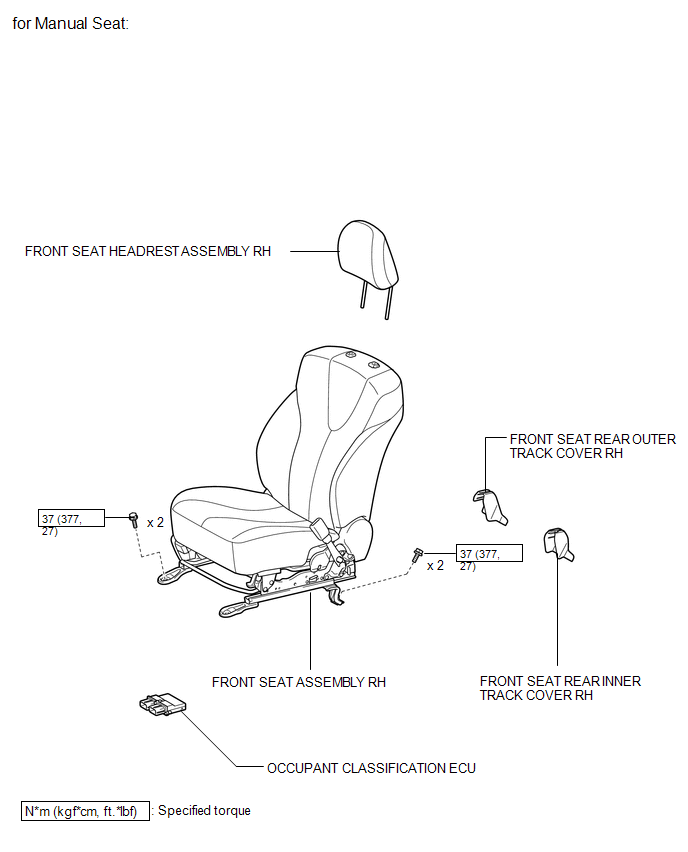
2. REMOVE FRONT SEAT ASSEMBLY RH
HINT:
Use the same procedure for the RH side and the LH side.
for Manual Seat: (See page )
for Power Seat: (See page )
3. REMOVE OCCUPANT CLASSIFICATION ECU
|
(a) Disconnect the connector from the occupant classification ECU. Text in Illustration
|
|
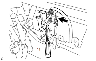
(b) Using a screwdriver with the tip wrapped with protective tape, disengage the claw to remove the occupant classification ECU.
Installation
INSTALLATION
PROCEDURE
1. INSTALL OCCUPANT CLASSIFICATION ECU
|
(a) Install the occupant classification ECU with the claw. NOTICE:
|
|
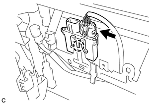
(b) Connect the connector.
2. INSTALL FRONT SEAT ASSEMBLY RH
HINT:
Use the same procedure for the RH side and the LH side.
for Manual Seat: (See page .gif) )
)
for Power Seat: (See page )
3. PERFORM DIAGNOSTIC SYSTEM CHECK
(a) Perform a diagnostic system check (See page
).
4. INSPECT SRS WARNING LIGHT
(a) Inspect the SRS warning light (See page
).
 Installation
INSTALLATION
PROCEDURE
1. INSTALL DRIVER SIDE KNEE AIRBAG ASSEMBLY
(a) Check that the ignition switch is off.
(b) Check that the cable is disconnected from the negative (-) battery terminal.
CAUT ...

Other materials about Toyota Venza:
Inspection
INSPECTION
PROCEDURE
1. INSPECT INTEGRATION RELAY
(a) Inner circuit (for 2GR-FE)
(1) for EFI MAIN relay
Measure the resistance according to the value(s) in the table
below.
Standard Resistance:
...
Tire size
- Typical tire size information
The illustration indicates typical tire size.
1. Tire use
(P = Passenger car, T = Temporary use)
2. Section width (millimeters)
3. Aspect ratio
(tire height to section width)
4. Tire construction code
(R = Radial ...
Relay
On-vehicle Inspection
ON-VEHICLE INSPECTION
PROCEDURE
1. FAN NO. 1 RELAY
(a) Remove the relay from the engine room relay block.
(b) Measure the resistance according to the value(s) in the table b ...

0.1313