
Toyota Venza: Multi-information display (TFT type)
The multi-information display presents the driver with a variety of driving-related data, including the clock and current outside temperature.
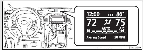
• Clock
Indicates and sets the time.
• Outside temperature
Indicates the outside temperature.
The temperature range that can be displayed is from -40°F (-40°C) to 122°F (50°C).
• Air conditioning system display
Automatically displayed when the air conditioning is turned on.
• Trip information
Displays driving range, fuel consumption and other cruising-related information.
• Intuitive parking assist display (if equipped)
• Warning messages
Automatically displayed when a malfunction occurs in one of the vehicle’s systems.
• Customizable features setting display
 Indicators and warning lights
The indicator and warning lights on the instrument cluster and center panel
inform the driver of the status of the vehicle’s various systems.
For the purpose of explanation, the following illustr ...
 Switching the display
1. “INFO” button
2. “SELECT RESET” button
To reset the functions below, press the “SELECT RESET” button.
• Average Fuel Economy
• Average Speed
• Trip Timer
3. “SETUP” bu ...
Other materials about Toyota Venza:
Rear Occupant Classification Sensor RH Collision Detection (B1788)
DESCRIPTION
DTC B1788 is output when the occupant classification ECU receives a collision
detection signal sent by the rear occupant classification sensor RH if an accident
occurs.
DTC B1788 is also output when the front seat assembly RH is subjected to ...
Vehicle Speed Sensor Malfunction (B2283)
DESCRIPTION
The skid control ECU converts wheel speed sensor signals into 4-pulse signals
and sends them to the combination meter. After this signal is converted into a more
precise rectangular waveform by the waveform shaping circuit inside the combinati ...
Back door
The back door can be opened using the back door opener. The back door can
be locked and unlocked using the entry function (vehicles with smart key system),
wireless remote control or door lock switch.
In addition, the power back door (if equipped) can be ...

0.1305